3-18 750/760 Feeder Management Relay GE Multilin
3.2 ELECTRICAL 3 INSTALLATION
3
3.2.11 RS232 COMMUNICATIONS
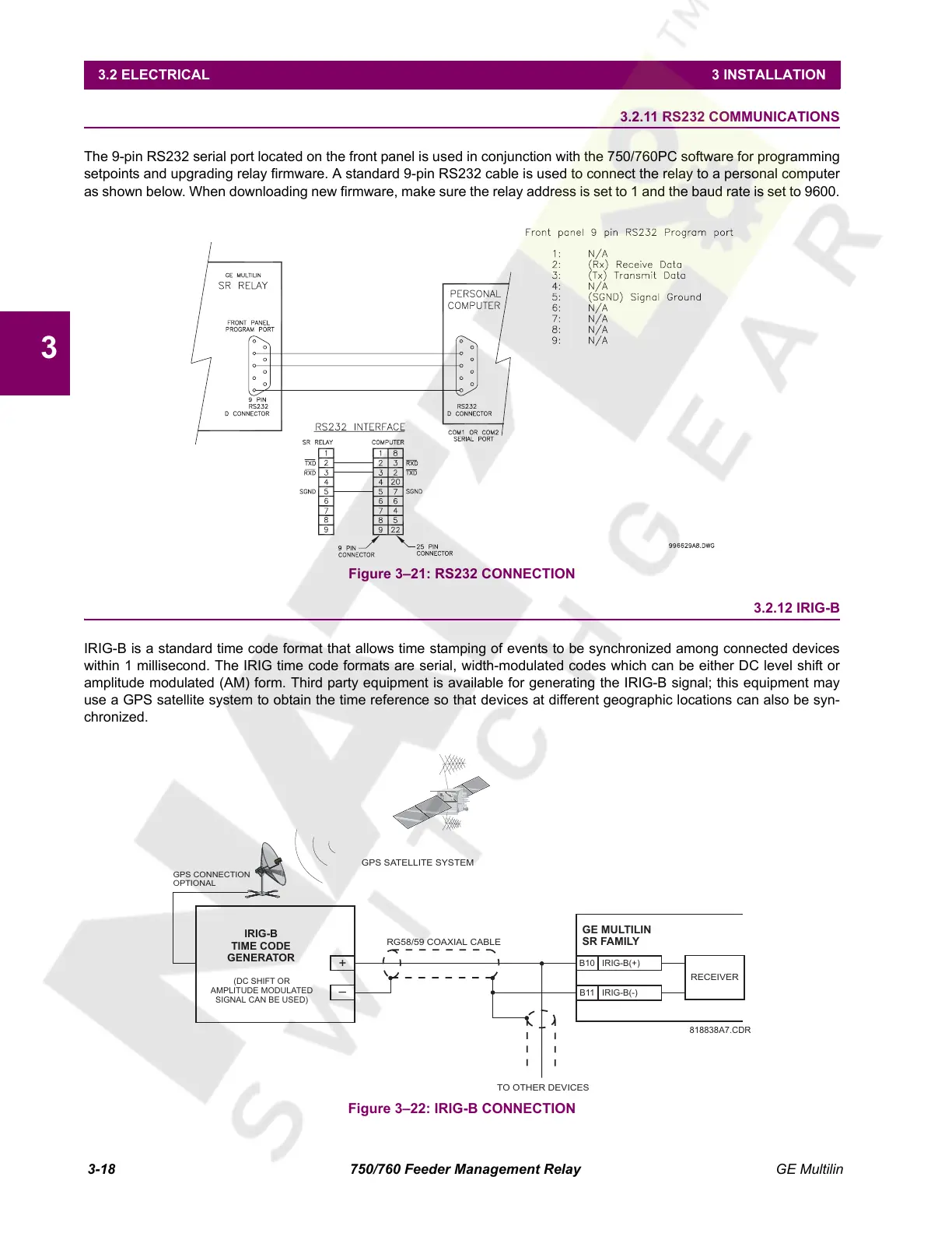
The 9-pin RS232 serial port located on the front panel is used in conjunction with the 750/760PC software for programming
setpoints and upgrading relay firmware. A standard 9-pin RS232 cable is used to connect the relay to a personal computer
as shown below. When downloading new firmware, make sure the relay address is set to 1 and the baud rate is set to 9600.
Figure 3–21: RS232 CONNECTION
3.2.12 IRIG-B
IRIG-B is a standard time code format that allows time stamping of events to be synchronized among connected devices
within 1 millisecond. The IRIG time code formats are serial, width-modulated codes which can be either DC level shift or
amplitude modulated (AM) form. Third party equipment is available for generating the IRIG-B signal; this equipment may
use a GPS satellite system to obtain the time reference so that devices at different geographic locations can also be syn-
chronized.
Figure 3–22: IRIG-B CONNECTION
GE MULTILIN
SR FAMILY
IRIG-B(-)
RECEIVER
TO OTHER DEVICES
RG58/59 COAXIAL CABLE
GPS SATELLITE SYSTEM
GPS CONNECTION
OPTIONAL
IRIG-B(+)
B10
B11
+
–
818838A7.CDR
IRIG-B
TIME CODE
GENERATOR
(DC SHIFT OR
AMPLITUDE MODULATED
SIGNAL CAN BE USED)
Courtesy of NationalSwitchgear.com
 Loading...


