GE Multilin 750/760 Feeder Management Relay 8-13
8 COMMISSIONING TESTS 8.3 METERING
8
d) POWER FACTOR
For these tests, refer to the figures on page 8–3 for test connections. The expected accuracy is as follows:
Power Factor: ±0.02 of injected values, currents 5 to 199% of nominal, voltages 50 to 130 V
The procedure for metered apparent power is as follows:
1. The relevant actual values displays are shown below:
A2 METERING ÖØ PWR ÖØ 3Φ PWR FACTOR:
A2 METERING ÖØ PWR ÖØ ΦA PWR FACTOR: (not available when connected Delta)
A2 METERING ÖØ PWR ÖØ ΦB PWR FACTOR: (not available when connected Delta)
A2 METERING ÖØ PWR ÖØ ΦC PWR FACTOR: (not available when connected Delta)
2. Inject 3-phase voltage and current of various values and angles into the relay. Verify that the power factor is measured
and displayed correctly for each phase. Note that:
(EQ 8.1)
8.3.4 DEMAND METERING
a) CURRENT DEMAND
For these tests, refer to the figures on page 8–3 for test connections. The expected accuracy is as follows:
Expected Accuracy: ±2.0% of full scale
To reset the "Last Demand" reading to 0 between tests, cycle the relay power source off and then on.
Block Interval and Rolling demand measurement types must be tested in synchronization with the internal clock. Both of
these measurements start with the first interval of the day at 12:00:00.000 midnight. To synchronize, preset the injection
levels, then turn the current off. Select the relay display (not the 750/760PC software) to
A1 STATUS ÖØ CLOCK ÖØ CUR-
RENT TIME. Apply the test current when the clock is at the beginning of an interval measurement period, as determined by
the TIME INTERVAL setpoint for the element.
The relevant actual values displays are shown below:
A2 METERING ÖØ DMND Ö PHASE A CURRENT Ö LAST PHASE A CURRENT DMND
A2 METERING ÖØ DMND Ö PHASE A CURRENT ÖØ MAX PHASE A CURRENT DMND
A2 METERING ÖØ DMND Ö PHASE A CURRENT ÖØ MAX PHASE A CURRENT DATE
A2 METERING ÖØ DMND ÖØ PHASE A CURRENT ÖØ MAX PHASE A CURRENT TIME
A2 METERING ÖØ DMND ÖØ PHASE B CURRENT Ö LAST PHASE B CURRENT DMND
A2 METERING ÖØ DMND ÖØ PHASE B CURRENT ÖØ MAX PHASE B CURRENT DMND
A2 METERING
ÖØ DMND ÖØ PHASE B CURRENT ÖØ MAX PHASE B CURRENT DATE
A2 METERING
ÖØ DMND ÖØ PHASE B CURRENT ÖØ MAX PHASE B CURRENT TIME
A2 METERING
ÖØ DMND ÖØ PHASE C CURRENT Ö LAST PHASE C CURRENT DMND
A2 METERING ÖØ DMND ÖØ PHASE C CURRENT ÖØ MAX PHASE C CURRENT DMND
A2 METERING ÖØ DMND ÖØ PHASE B CURRENT ÖØ MAX PHASE C CURRENT DATE
A2 METERING
ÖØ DMND ÖØ PHASE B CURRENT ÖØ MAX PHASE C CURRENT TIME
For Thermal Exponential Demand (for example, a response time setting of 5 minutes), the procedure is as follows:
1. Clear demand data registers by setting S1 RELAY SETUP ÖØ CLEAR DATA ÖØ CLEAR MAX DMND DATA to “Yes”.
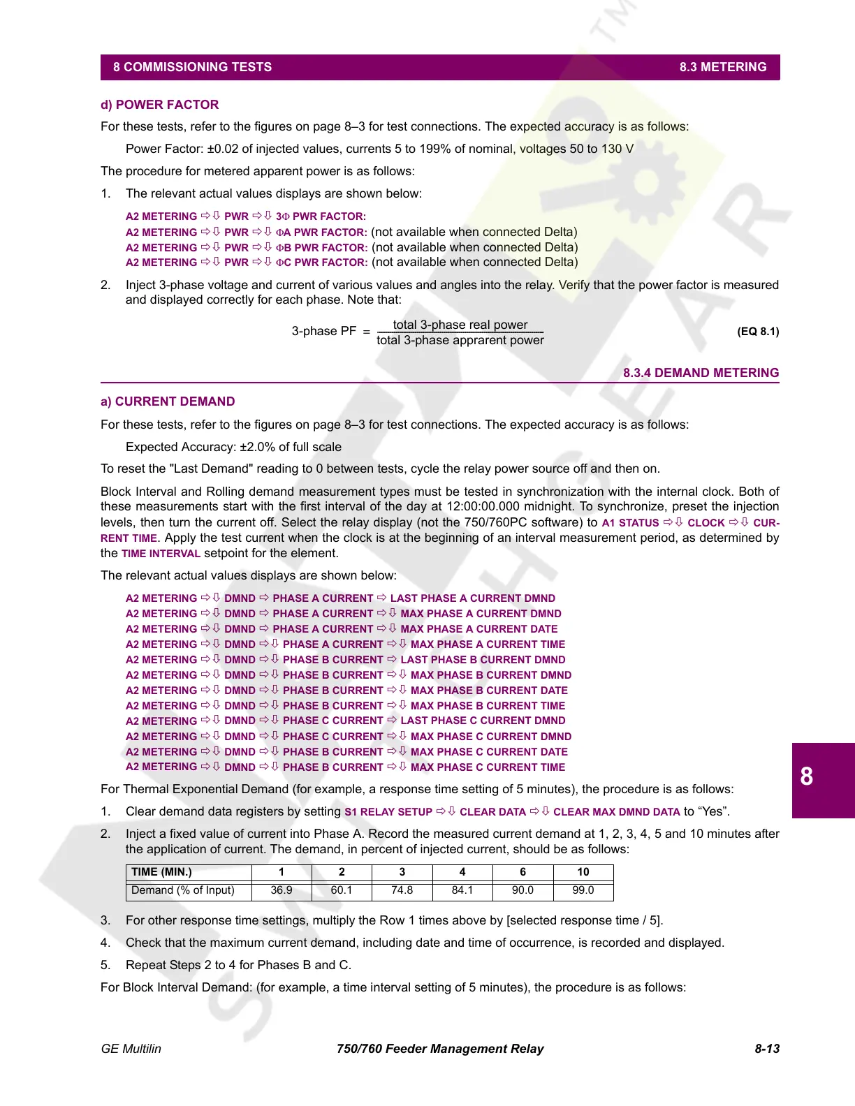
2. Inject a fixed value of current into Phase A. Record the measured current demand at 1, 2, 3, 4, 5 and 10 minutes after
the application of current. The demand, in percent of injected current, should be as follows:
3. For other response time settings, multiply the Row 1 times above by [selected response time / 5].
4. Check that the maximum current demand, including date and time of occurrence, is recorded and displayed.
5. Repeat Steps 2 to 4 for Phases B and C.
For Block Interval Demand: (for example, a time interval setting of 5 minutes), the procedure is as follows:
TIME (MIN.) 1234610
Demand (% of Input) 36.9 60.1 74.8 84.1 90.0 99.0
3-phase PF
total 3-phase real power
total 3-phase apprarent power
------------------------------------------------------------------------------- -=
Courtesy of NationalSwitchgear.com
 Loading...


