8-14 750/760 Feeder Management Relay GE Multilin
8.3 METERING 8 COMMISSIONING TESTS
8
1. Repeat Steps 2 to 5 above.
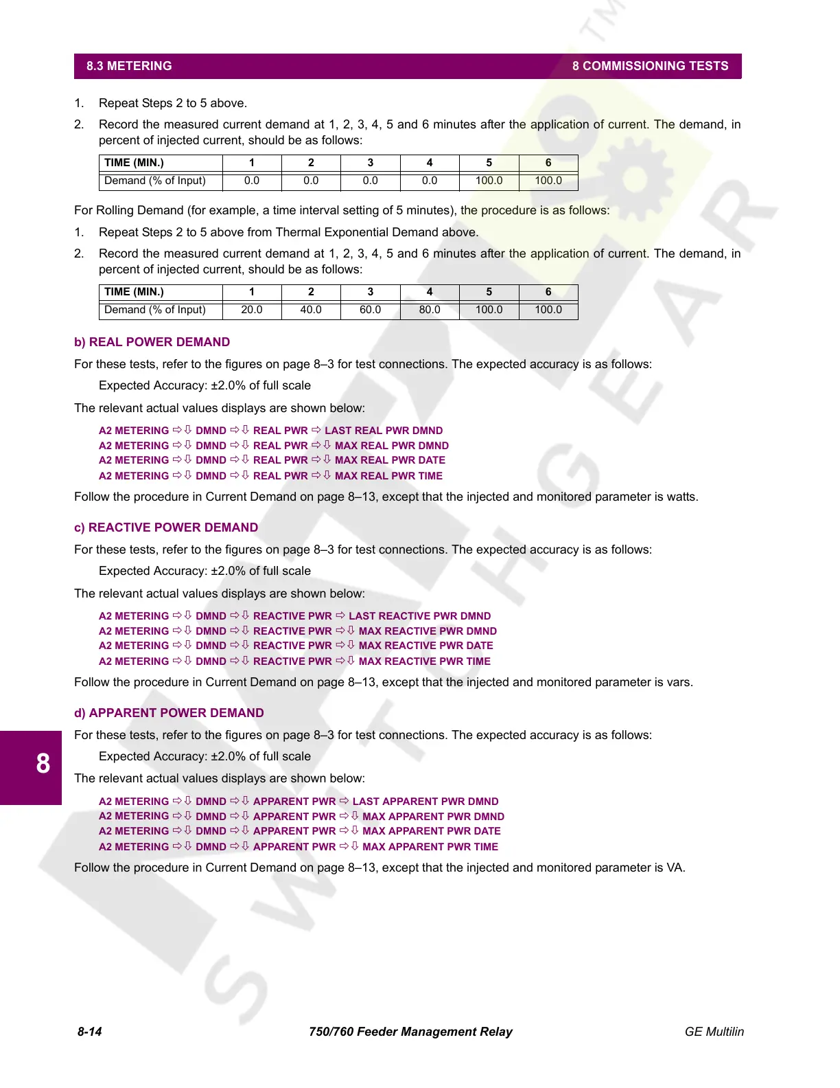
2. Record the measured current demand at 1, 2, 3, 4, 5 and 6 minutes after the application of current. The demand, in
percent of injected current, should be as follows:
For Rolling Demand (for example, a time interval setting of 5 minutes), the procedure is as follows:
1. Repeat Steps 2 to 5 above from Thermal Exponential Demand above.
2. Record the measured current demand at 1, 2, 3, 4, 5 and 6 minutes after the application of current. The demand, in
percent of injected current, should be as follows:
b) REAL POWER DEMAND
For these tests, refer to the figures on page 8–3 for test connections. The expected accuracy is as follows:
Expected Accuracy: ±2.0% of full scale
The relevant actual values displays are shown below:
A2 METERING ÖØ DMND ÖØ REAL PWR Ö LAST REAL PWR DMND
A2 METERING ÖØ DMND ÖØ REAL PWR ÖØ MAX REAL PWR DMND
A2 METERING ÖØ DMND ÖØ REAL PWR ÖØ MAX REAL PWR DATE
A2 METERING ÖØ DMND ÖØ REAL PWR ÖØ MAX REAL PWR TIME
Follow the procedure in Current Demand on page 8–13, except that the injected and monitored parameter is watts.
c) REACTIVE POWER DEMAND
For these tests, refer to the figures on page 8–3 for test connections. The expected accuracy is as follows:
Expected Accuracy: ±2.0% of full scale
The relevant actual values displays are shown below:
A2 METERING ÖØ DMND ÖØ REACTIVE PWR Ö LAST REACTIVE PWR DMND
A2 METERING ÖØ DMND ÖØ REACTIVE PWR ÖØ MAX REACTIVE PWR DMND
A2 METERING ÖØ DMND ÖØ REACTIVE PWR ÖØ MAX REACTIVE PWR DATE
A2 METERING ÖØ DMND ÖØ REACTIVE PWR ÖØ MAX REACTIVE PWR TIME
Follow the procedure in Current Demand on page 8–13, except that the injected and monitored parameter is vars.
d) APPARENT POWER DEMAND
For these tests, refer to the figures on page 8–3 for test connections. The expected accuracy is as follows:
Expected Accuracy: ±2.0% of full scale
The relevant actual values displays are shown below:
A2 METERING ÖØ DMND ÖØ APPARENT PWR Ö LAST APPARENT PWR DMND
A2 METERING
ÖØ DMND ÖØ APPARENT PWR ÖØ MAX APPARENT PWR DMND
A2 METERING
ÖØ DMND ÖØ APPARENT PWR ÖØ MAX APPARENT PWR DATE
A2 METERING ÖØ DMND ÖØ APPARENT PWR ÖØ MAX APPARENT PWR TIME
Follow the procedure in Current Demand on page 8–13, except that the injected and monitored parameter is VA.
TIME (MIN.) 123456
Demand (% of Input) 0.0 0.0 0.0 0.0 100.0 100.0
TIME (MIN.) 123456
Demand (% of Input) 20.0 40.0 60.0 80.0 100.0 100.0
Courtesy of NationalSwitchgear.com
 Loading...


