5-30 750/760 Feeder Management Relay GE Multilin
5.5 S4 OUTPUT RELAYS 5 SETPOINTS
5
5.5.4 AUXILIARY RELAYS
PATH: SETPOINTS ÖØ S4 OUTPUT RELAYS ÖØ 3(7) AUX RELAY
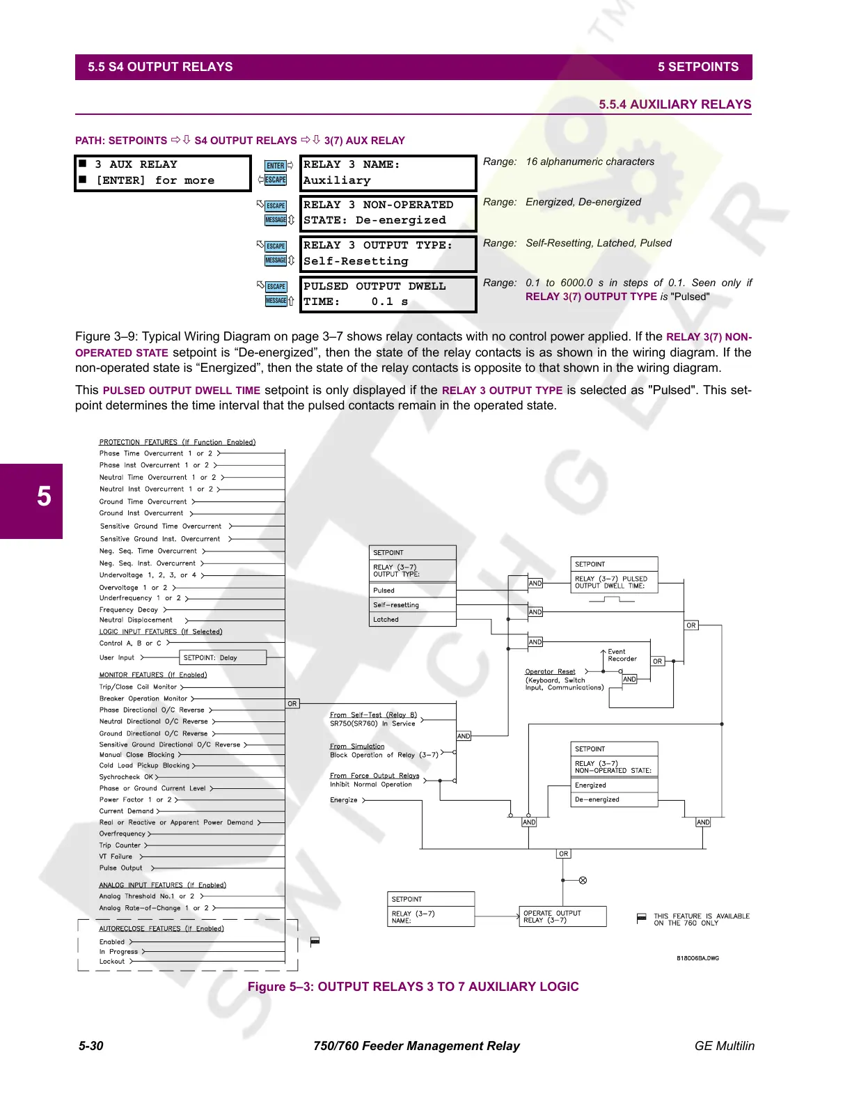
Figure 3–9: Typical Wiring Diagram on page 3–7 shows relay contacts with no control power applied. If the RELAY 3(7) NON-
OPERATED STATE setpoint is “De-energized”, then the state of the relay contacts is as shown in the wiring diagram. If the
non-operated state is “Energized”, then the state of the relay contacts is opposite to that shown in the wiring diagram.
This PULSED OUTPUT DWELL TIME setpoint is only displayed if the RELAY 3 OUTPUT TYPE is selected as "Pulsed". This set-
point determines the time interval that the pulsed contacts remain in the operated state.
Figure 5–3: OUTPUT RELAYS 3 TO 7 AUXILIARY LOGIC
3 AUX RELAY
[ENTER] for more
RELAY 3 NAME:
Auxiliary
Range: 16 alphanumeric characters
RELAY 3 NON-OPERATED
STATE: De-energized
Range: Energized, De-energized
RELAY 3 OUTPUT TYPE:
Self-Resetting
Range: Self-Resetting, Latched, Pulsed
PULSED OUTPUT DWELL
TIME: 0.1 s
Range: 0.1 to 6000.0 s in steps of 0.1. Seen only if
RELAY 3(7) OUTPUT TYPE is "Pulsed"
ENTER
ESCAPE
ð
ð
MESSAGE
ESCAPE
MESSAGE
ESCAPE
MESSAGE
ESCAPE
Courtesy of NationalSwitchgear.com
 Loading...


