GE Multilin 750/760 Feeder Management Relay 1-5
1 GETTING STARTED 1.2 USING THE RELAY
1
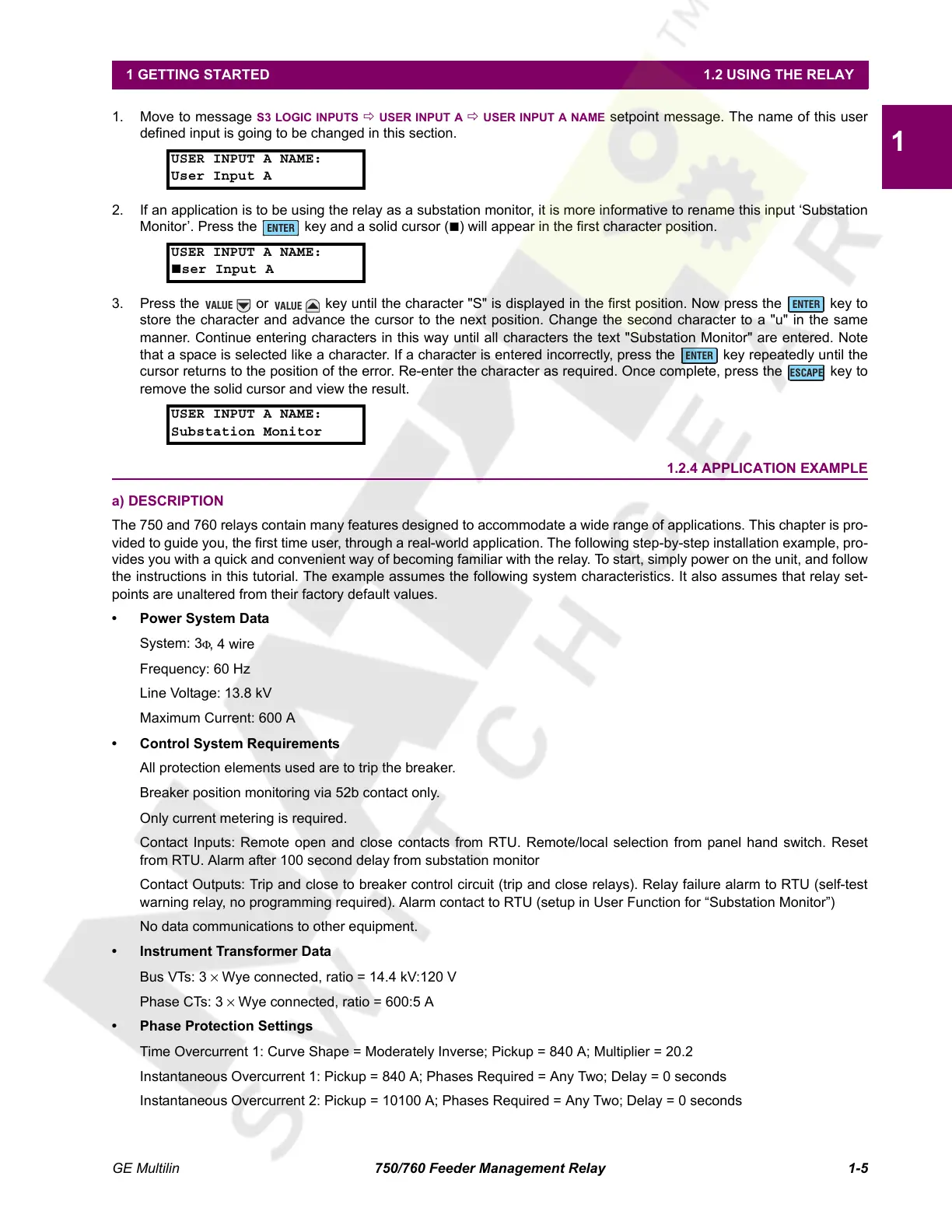
1. Move to message S3 LOGIC INPUTS Ö USER INPUT A Ö USER INPUT A NAME setpoint message. The name of this user
defined input is going to be changed in this section.
2. If an application is to be using the relay as a substation monitor, it is more informative to rename this input ‘Substation
Monitor’. Press the key and a solid cursor () will appear in the first character position.
3. Press the or key until the character "S" is displayed in the first position. Now press the key to
store the character and advance the cursor to the next position. Change the second character to a "u" in the same
manner. Continue entering characters in this way until all characters the text "Substation Monitor" are entered. Note
that a space is selected like a character. If a character is entered incorrectly, press the key repeatedly until the
cursor returns to the position of the error. Re-enter the character as required. Once complete, press the key to
remove the solid cursor and view the result.
1.2.4 APPLICATION EXAMPLE
a) DESCRIPTION
The 750 and 760 relays contain many features designed to accommodate a wide range of applications. This chapter is pro-
vided to guide you, the first time user, through a real-world application. The following step-by-step installation example, pro-
vides you with a quick and convenient way of becoming familiar with the relay. To start, simply power on the unit, and follow
the instructions in this tutorial. The example assumes the following system characteristics. It also assumes that relay set-
points are unaltered from their factory default values.
• Power System Data
System: 3
Φ, 4 wire
Frequency: 60 Hz
Line Voltage: 13.8 kV
Maximum Current: 600 A
• Control System Requirements
All protection elements used are to trip the breaker.
Breaker position monitoring via 52b contact only.
Only current metering is required.
Contact Inputs: Remote open and close contacts from RTU. Remote/local selection from panel hand switch. Reset
from RTU. Alarm after 100 second delay from substation monitor
Contact Outputs: Trip and close to breaker control circuit (trip and close relays). Relay failure alarm to RTU (self-test
warning relay, no programming required). Alarm contact to RTU (setup in User Function for “Substation Monitor”)
No data communications to other equipment.
• Instrument Transformer Data
Bus VTs: 3 × Wye connected, ratio = 14.4 kV:120 V
Phase CTs: 3 × Wye connected, ratio = 600:5 A
• Phase Protection Settings
Time Overcurrent 1: Curve Shape = Moderately Inverse; Pickup = 840 A; Multiplier = 20.2
Instantaneous Overcurrent 1: Pickup = 840 A; Phases Required = Any Two; Delay = 0 seconds
Instantaneous Overcurrent 2: Pickup = 10100 A; Phases Required = Any Two; Delay = 0 seconds
USER INPUT A NAME:
User Input A
USER INPUT A NAME:
ser Input A
USER INPUT A NAME:
Substation Monitor
ENTER
VALUE
VALUE
ENTER
ENTER
ESCAPE
Courtesy of NationalSwitchgear.com
 Loading...


