5-132 750/760 Feeder Management Relay GE Multilin
5.9 S8 TESTING 5 SETPOINTS
5
The relay remains in the Prefault State until a command is received to enter the Fault State, either by setting the SIMU-
LATION STATE setpoint to the Fault State, or a contact closure on a logic input whose function setpoint is set to Simulate
Fault. The logic input makes the measurement of feature operating times possible when output relays are allowed to
operate.
In the Fault State, relay features respond to the programmed fault values, generating a trip, alarms, event records, trig-
gers of trace memory and data logger, and front panel indications as necessary. Output relays only operate if permitted
by the
ALLOW OPERATION OF RELAYS (3-7) setpoint. The relay remains in the Fault State until it has detected a trip con-
dition. Note that the Trip Relay is not allowed to operate. At this time the simulated breaker is opened (as indicated by
front panel indicators) and the relay is placed in Postfault State.
The relay remains in the Postfault State until either a close command received or the 760 autoreclose scheme has all
requirements met and is ready to close. At this time the relay returns to the Prefault State. Note that the Close Relay is
not allowed to operate. Setting the
SIMULATION STATE setpoint to "Disabled" also terminates simulation.
2. If simulation of the feeder breaker is not required set the Circuit Breaker Simulation setpoint to Disabled. After the
required simulation setpoints have been entered, the relay is placed in simulation mode by setting the SIMULATION
STATE setpoint to "Prefault". The relay replaces the normal AC inputs with those programmed on the Prefault Values
setpoint page. All logic inputs are monitored normally throughout the simulation including any set to monitor the 52a/
52b contacts by which the front panel Breaker Open and Breaker Closed indicators are set.
Operation is similar to that described in Method 1 above except that the Trip Relay will operate if a trip condition is
declared and the Close Relay will operate in response to any form of close request. As well, the Simulation State is
controlled by the monitored state of the breaker.
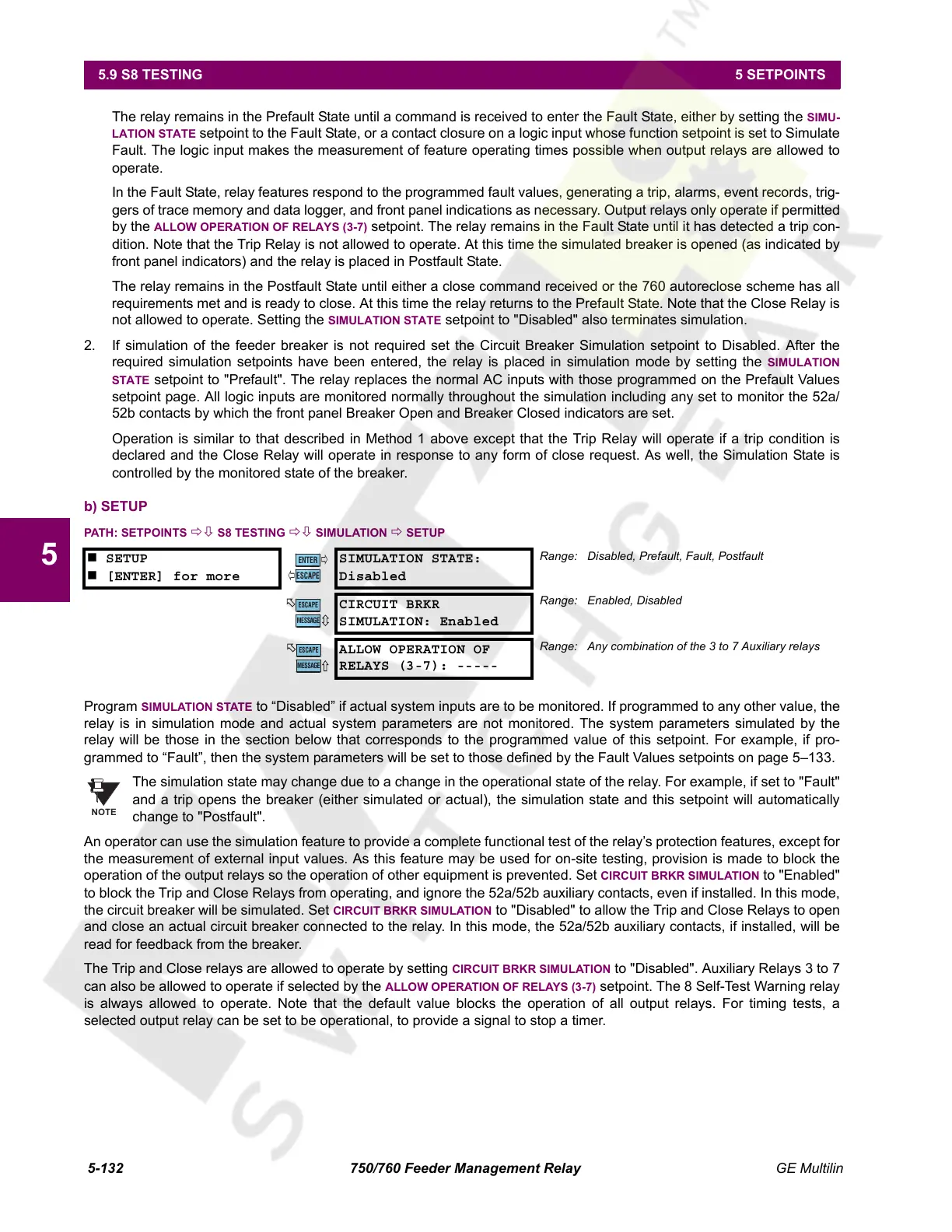
b) SETUP
PATH: SETPOINTS ÖØ S8 TESTING ÖØ SIMULATION Ö SETUP
Program SIMULATION STATE to “Disabled” if actual system inputs are to be monitored. If programmed to any other value, the
relay is in simulation mode and actual system parameters are not monitored. The system parameters simulated by the
relay will be those in the section below that corresponds to the programmed value of this setpoint. For example, if pro-
grammed to “Fault”, then the system parameters will be set to those defined by the Fault Values setpoints on page 5–133.
The simulation state may change due to a change in the operational state of the relay. For example, if set to "Fault"
and a trip opens the breaker (either simulated or actual), the simulation state and this setpoint will automatically
change to "Postfault".
An operator can use the simulation feature to provide a complete functional test of the relay’s protection features, except for
the measurement of external input values. As this feature may be used for on-site testing, provision is made to block the
operation of the output relays so the operation of other equipment is prevented. Set
CIRCUIT BRKR SIMULATION to "Enabled"
to block the Trip and Close Relays from operating, and ignore the 52a/52b auxiliary contacts, even if installed. In this mode,
the circuit breaker will be simulated. Set
CIRCUIT BRKR SIMULATION to "Disabled" to allow the Trip and Close Relays to open
and close an actual circuit breaker connected to the relay. In this mode, the 52a/52b auxiliary contacts, if installed, will be
read for feedback from the breaker.
The Trip and Close relays are allowed to operate by setting
CIRCUIT BRKR SIMULATION to "Disabled". Auxiliary Relays 3 to 7
can also be allowed to operate if selected by the
ALLOW OPERATION OF RELAYS (3-7) setpoint. The 8 Self-Test Warning relay
is always allowed to operate. Note that the default value blocks the operation of all output relays. For timing tests, a
selected output relay can be set to be operational, to provide a signal to stop a timer.
SETUP
[ENTER] for more
SIMULATION STATE:
Disabled
Range: Disabled, Prefault, Fault, Postfault
CIRCUIT BRKR
SIMULATION: Enabled
Range: Enabled, Disabled
ALLOW OPERATION OF
RELAYS (3-7): -----
Range: Any combination of the 3 to 7 Auxiliary relays
ENTER
ESCAPE
ð
ð
MESSAGE
ESCAPE
MESSAGE
ESCAPE
NOTE
Courtesy of NationalSwitchgear.com
 Loading...


