GE Multilin 750/760 Feeder Management Relay 5-87
5 SETPOINTS 5.7 S6 MONITORING
5
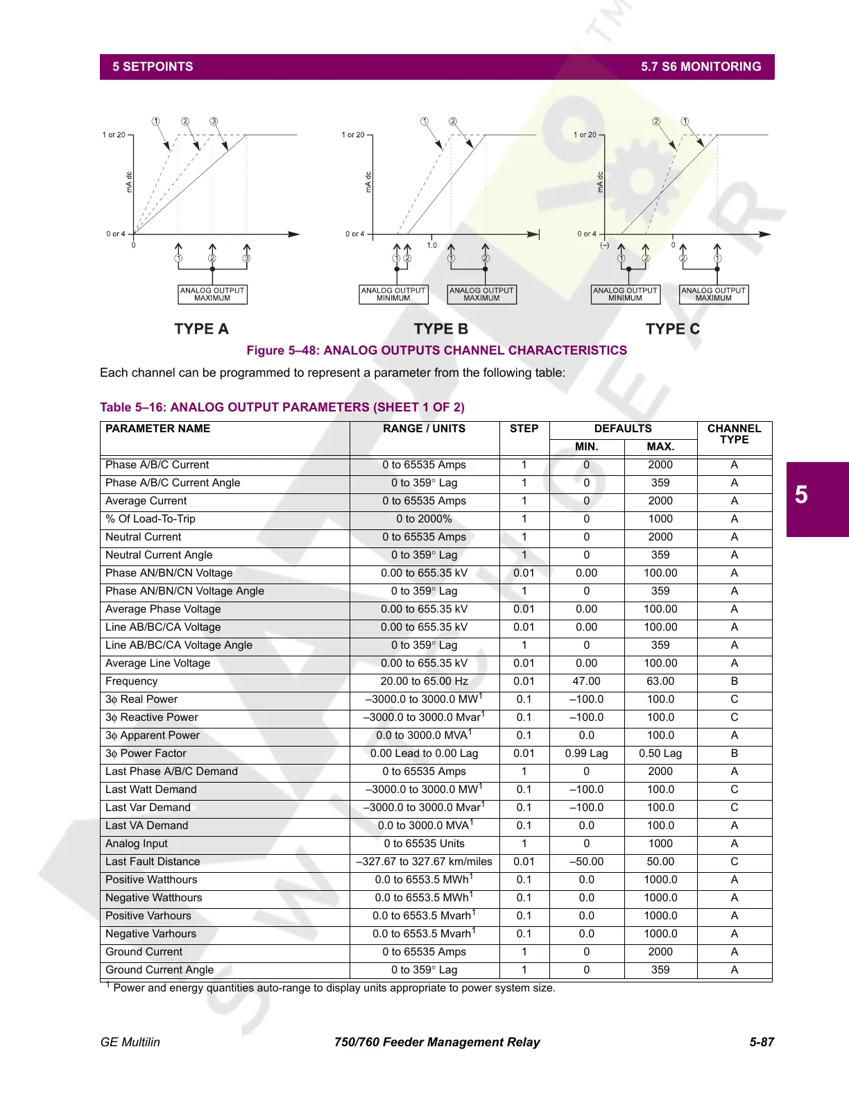
Figure 5–48: ANALOG OUTPUTS CHANNEL CHARACTERISTICS
Each channel can be programmed to represent a parameter from the following table:
Table 5–16: ANALOG OUTPUT PARAMETERS (SHEET 1 OF 2)
PARAMETER NAME RANGE / UNITS STEP DEFAULTS CHANNEL
TYPE
MIN. MAX.
Phase A/B/C Current 0 to 65535 Amps 1 0 2000 A
Phase A/B/C Current Angle 0 to 359° Lag 1 0 359 A
Average Current 0 to 65535 Amps 1 0 2000 A
% Of Load-To-Trip 0 to 2000% 1 0 1000 A
Neutral Current 0 to 65535 Amps 1 0 2000 A
Neutral Current Angle 0 to 359° Lag 1 0 359 A
Phase AN/BN/CN Voltage 0.00 to 655.35 kV 0.01 0.00 100.00 A
Phase AN/BN/CN Voltage Angle 0 to 359° Lag 1 0 359 A
Average Phase Voltage 0.00 to 655.35 kV 0.01 0.00 100.00 A
Line AB/BC/CA Voltage 0.00 to 655.35 kV 0.01 0.00 100.00 A
Line AB/BC/CA Voltage Angle 0 to 359° Lag 1 0 359 A
Average Line Voltage 0.00 to 655.35 kV 0.01 0.00 100.00 A
Frequency 20.00 to 65.00 Hz 0.01 47.00 63.00 B
3φ Real Power –3000.0 to 3000.0 MW
1
0.1 –100.0 100.0 C
3φ Reactive Power –3000.0 to 3000.0 Mvar
1
0.1 –100.0 100.0 C
3φ Apparent Power 0.0 to 3000.0 MVA
1
0.1 0.0 100.0 A
3φ Power Factor 0.00 Lead to 0.00 Lag 0.01 0.99 Lag 0.50 Lag B
Last Phase A/B/C Demand 0 to 65535 Amps 1 0 2000 A
Last Watt Demand –3000.0 to 3000.0 MW
1
0.1 –100.0 100.0 C
Last Var Demand –3000.0 to 3000.0 Mvar
1
0.1 –100.0 100.0 C
Last VA Demand 0.0 to 3000.0 MVA
1
0.1 0.0 100.0 A
Analog Input 0 to 65535 Units 1 0 1000 A
Last Fault Distance –327.67 to 327.67 km/miles 0.01 –50.00 50.00 C
Positive Watthours 0.0 to 6553.5 MWh
1
0.1 0.0 1000.0 A
Negative Watthours 0.0 to 6553.5 MWh
1
0.1 0.0 1000.0 A
Positive Varhours 0.0 to 6553.5 Mvarh
1
0.1 0.0 1000.0 A
Negative Varhours 0.0 to 6553.5 Mvarh
1
0.1 0.0 1000.0 A
Ground Current 0 to 65535 Amps 1 0 2000 A
Ground Current Angle 0 to 359° Lag 1 0 359 A
1
Power and energy quantities auto-range to display units appropriate to power system size.
Courtesy of NationalSwitchgear.com
 Loading...


