5-100 750/760 Feeder Management Relay GE Multilin
5.8 S7 CONTROL 5 SETPOINTS
5
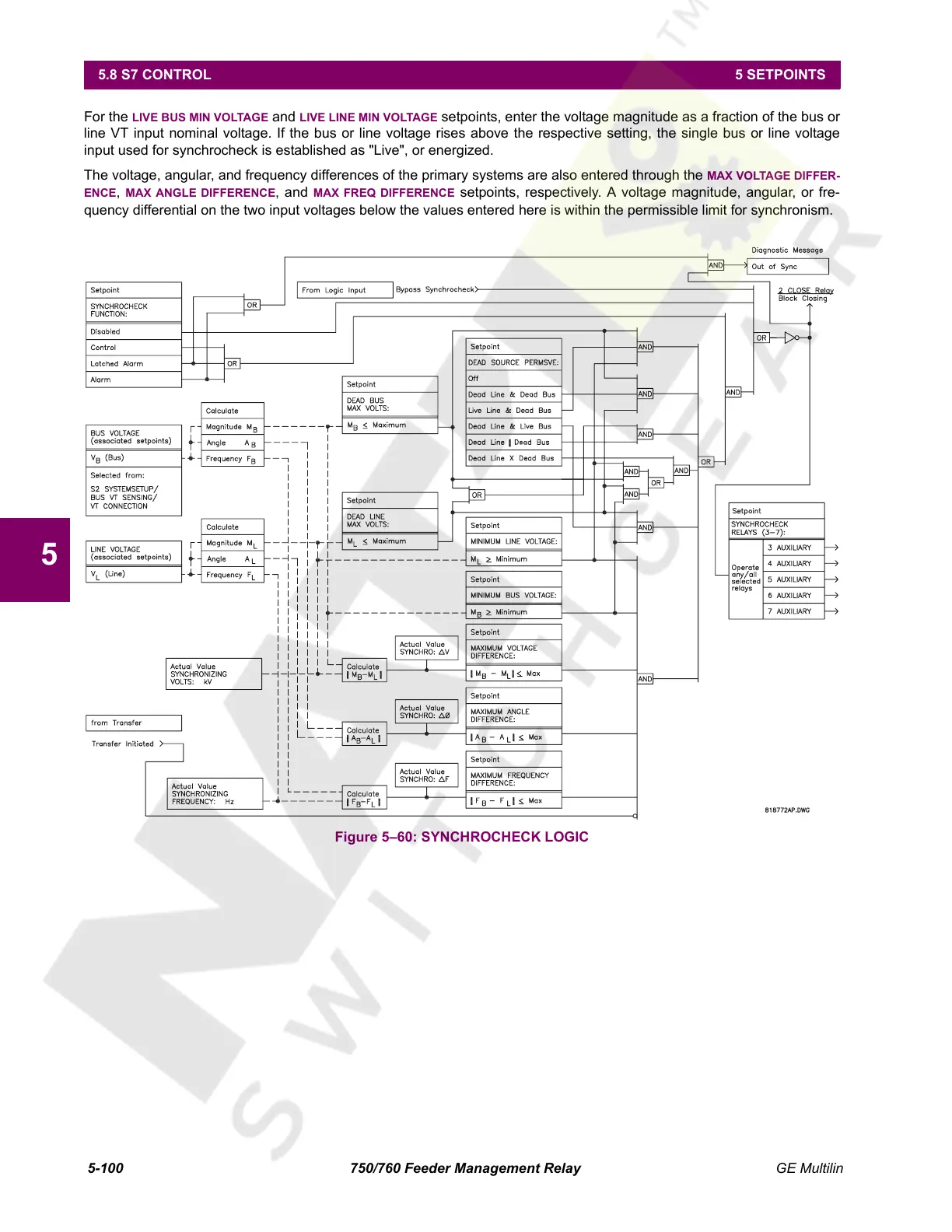
For the LIVE BUS MIN VOLTAGE and LIVE LINE MIN VOLTAGE setpoints, enter the voltage magnitude as a fraction of the bus or
line VT input nominal voltage. If the bus or line voltage rises above the respective setting, the single bus or line voltage
input used for synchrocheck is established as "Live", or energized.
The voltage, angular, and frequency differences of the primary systems are also entered through the MAX VOLTAGE DIFFER-
ENCE, MAX ANGLE DIFFERENCE, and MAX FREQ DIFFERENCE setpoints, respectively. A voltage magnitude, angular, or fre-
quency differential on the two input voltages below the values entered here is within the permissible limit for synchronism.
Figure 5–60: SYNCHROCHECK LOGIC
Courtesy of NationalSwitchgear.com
 Loading...


