GE Multilin 750/760 Feeder Management Relay 5-61
5 SETPOINTS 5.6 S5 PROTECTION
5
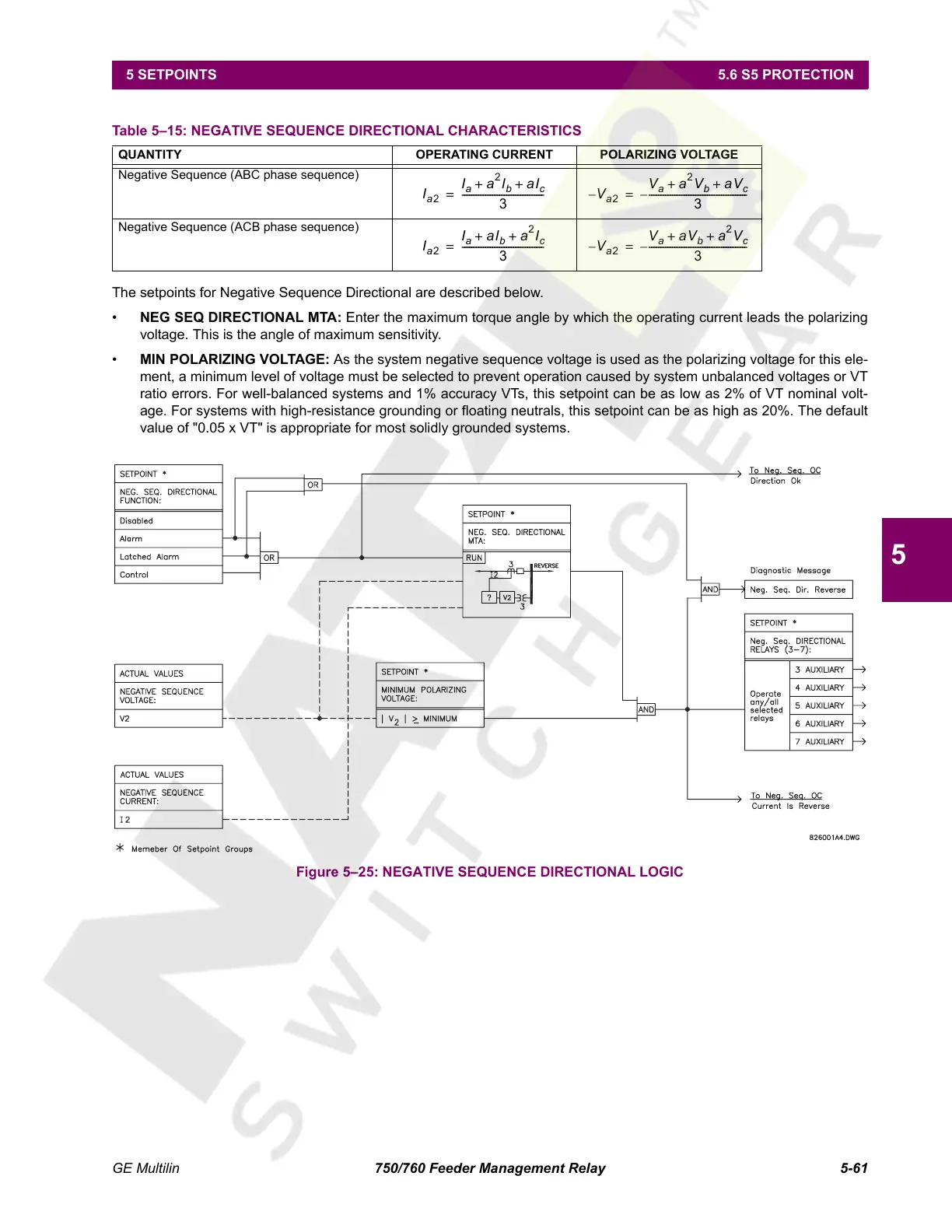
The setpoints for Negative Sequence Directional are described below.
• NEG SEQ DIRECTIONAL MTA: Enter the maximum torque angle by which the operating current leads the polarizing
voltage. This is the angle of maximum sensitivity.
• MIN POLARIZING VOLTAGE: As the system negative sequence voltage is used as the polarizing voltage for this ele-
ment, a minimum level of voltage must be selected to prevent operation caused by system unbalanced voltages or VT
ratio errors. For well-balanced systems and 1% accuracy VTs, this setpoint can be as low as 2% of VT nominal volt-
age. For systems with high-resistance grounding or floating neutrals, this setpoint can be as high as 20%. The default
value of "0.05 x VT" is appropriate for most solidly grounded systems.
Figure 5–25: NEGATIVE SEQUENCE DIRECTIONAL LOGIC
Table 5–15: NEGATIVE SEQUENCE DIRECTIONAL CHARACTERISTICS
QUANTITY OPERATING CURRENT POLARIZING VOLTAGE
Negative Sequence (ABC phase sequence)
Negative Sequence (ACB phase sequence)
I
a2
I
a
a
2
I
b
aI
c
++
3
-----------------------------------= V–
a2
V
a
a
2
V
b
aV
c
++
3
------------------------------------------–=
I
a2
I
a
aI
b
a
2
I
c
++
3
-----------------------------------= V–
a2
V
a
aV
b
a
2
V
c
++
3
------------------------------------------–=
Courtesy of NationalSwitchgear.com
 Loading...


