5-70 750/760 Feeder Management Relay GE Multilin
5.6 S5 PROTECTION 5 SETPOINTS
5
c) FREQUENCY DECAY
PATH: SETPOINTS ÖØ S5 PROTECTION ÖØ FREQ ÖØ FREQ DECAY
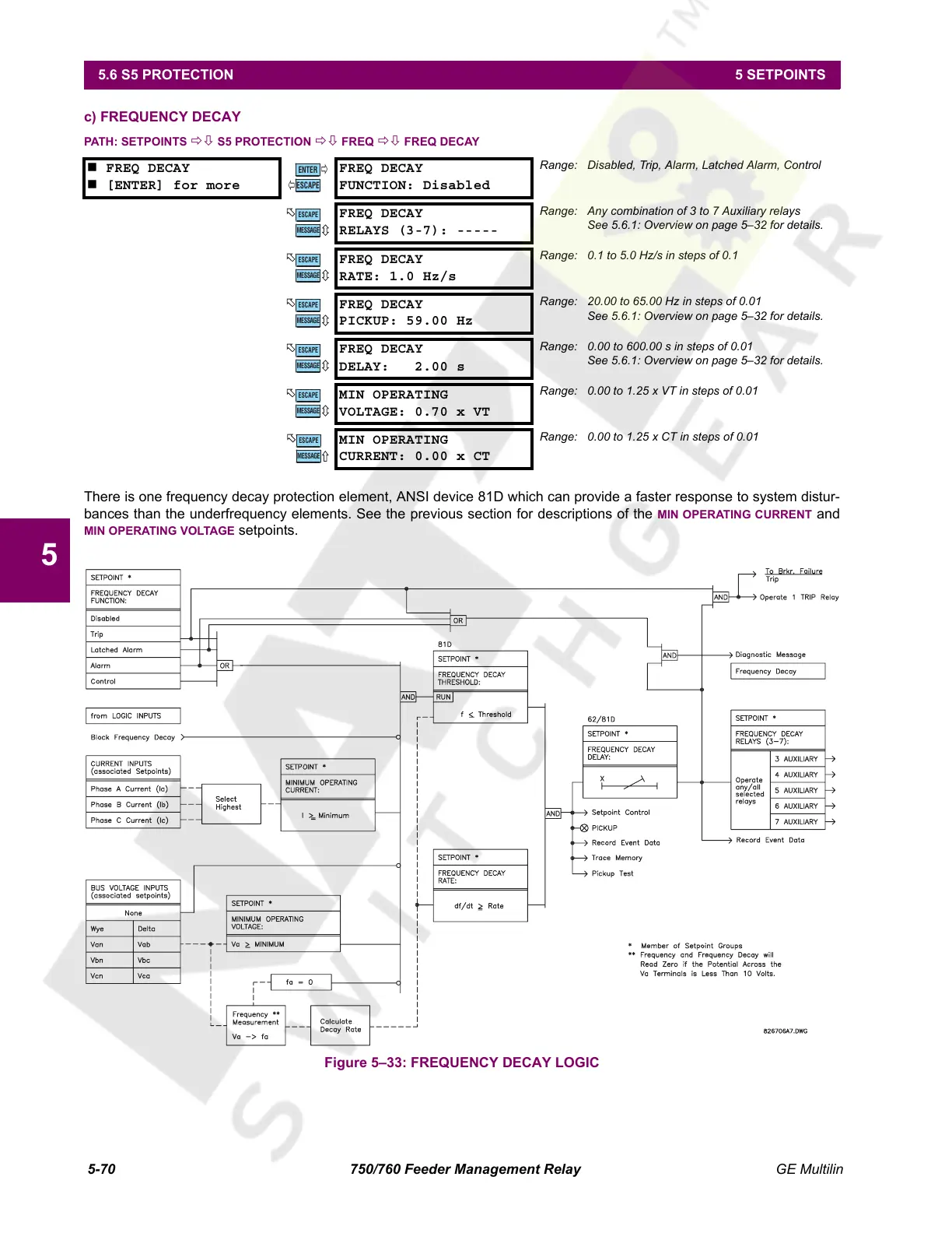
There is one frequency decay protection element, ANSI device 81D which can provide a faster response to system distur-
bances than the underfrequency elements. See the previous section for descriptions of the MIN OPERATING CURRENT and
MIN OPERATING VOLTAGE setpoints.
Figure 5–33: FREQUENCY DECAY LOGIC
FREQ DECAY
[ENTER] for more
FREQ DECAY
FUNCTION: Disabled
Range: Disabled, Trip, Alarm, Latched Alarm, Control
FREQ DECAY
RELAYS (3-7): -----
Range: Any combination of 3 to 7 Auxiliary relays
See 5.6.1: Overview on page 5–32 for details.
FREQ DECAY
RATE: 1.0 Hz/s
Range: 0.1 to 5.0 Hz/s in steps of 0.1
FREQ DECAY
PICKUP: 59.00 Hz
Range: 20.00 to 65.00 Hz in steps of 0.01
See 5.6.1: Overview on page 5–32 for details.
FREQ DECAY
DELAY: 2.00 s
Range: 0.00 to 600.00 s in steps of 0.01
See 5.6.1: Overview on page 5–32 for details.
MIN OPERATING
VOLTAGE: 0.70 x VT
Range: 0.00 to 1.25 x VT in steps of 0.01
MIN OPERATING
CURRENT: 0.00 x CT
Range: 0.00 to 1.25 x CT in steps of 0.01
ENTER
ESCAPE
ð
ð
MESSAGE
ESCAPE
MESSAGE
ESCAPE
MESSAGE
ESCAPE
MESSAGE
ESCAPE
MESSAGE
ESCAPE
MESSAGE
ESCAPE
Courtesy of NationalSwitchgear.com
 Loading...


