GE Multilin 750/760 Feeder Management Relay 5-81
5 SETPOINTS 5.7 S6 MONITORING
5
d) REACTIVE POWER DEMAND
PATH: SETPOINTS ÖØ S6 MONITORING ÖØ DMND ÖØ REAL PWR
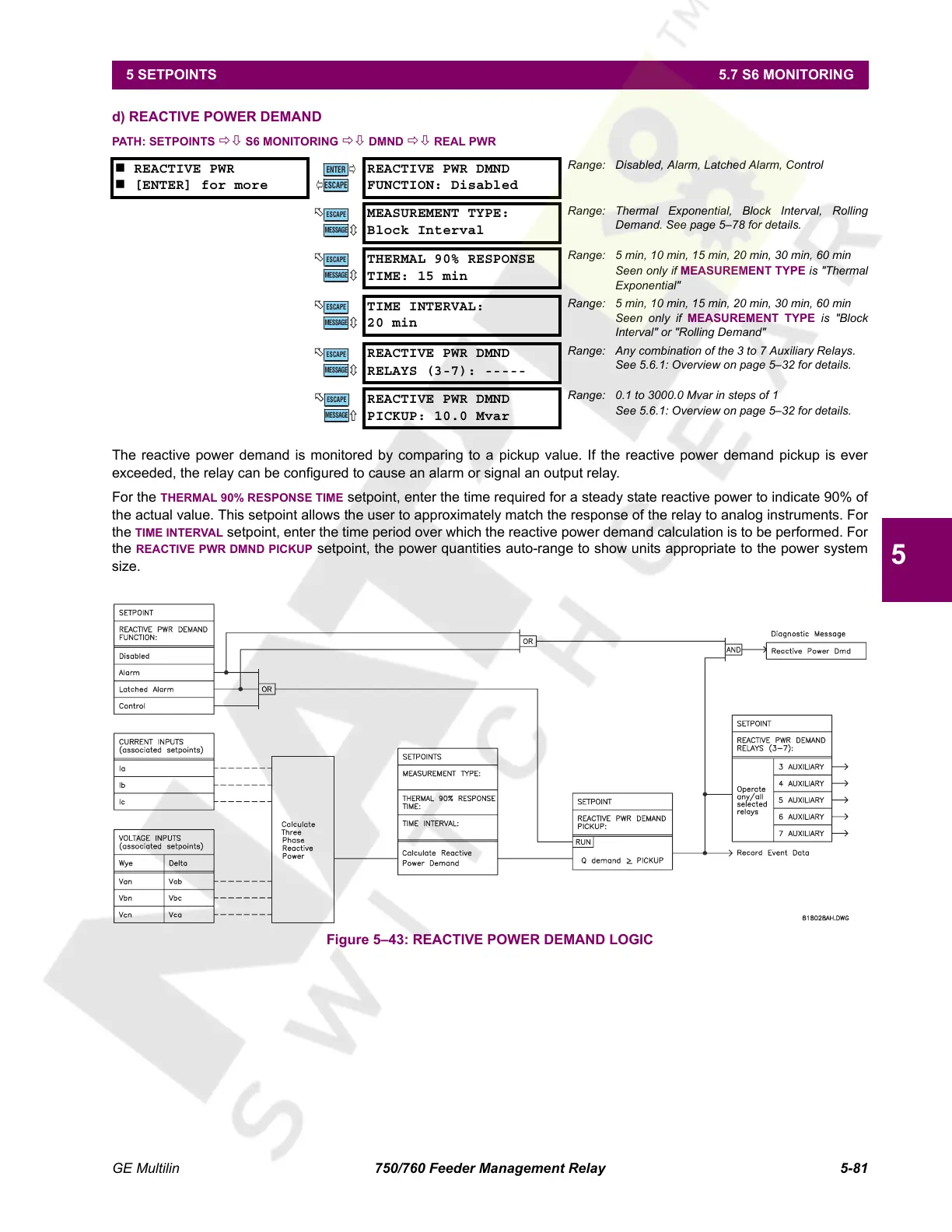
The reactive power demand is monitored by comparing to a pickup value. If the reactive power demand pickup is ever
exceeded, the relay can be configured to cause an alarm or signal an output relay.
For the THERMAL 90% RESPONSE TIME setpoint, enter the time required for a steady state reactive power to indicate 90% of
the actual value. This setpoint allows the user to approximately match the response of the relay to analog instruments. For
the
TIME INTERVAL setpoint, enter the time period over which the reactive power demand calculation is to be performed. For
the REACTIVE PWR DMND PICKUP setpoint, the power quantities auto-range to show units appropriate to the power system
size.
Figure 5–43: REACTIVE POWER DEMAND LOGIC
REACTIVE PWR
[ENTER] for more
REACTIVE PWR DMND
FUNCTION: Disabled
Range: Disabled, Alarm, Latched Alarm, Control
MEASUREMENT TYPE:
Block Interval
Range: Thermal Exponential, Block Interval, Rolling
Demand. See page 5–78 for details.
THERMAL 90% RESPONSE
TIME: 15 min
Range: 5 min, 10 min, 15 min, 20 min, 30 min, 60 min
Seen only if MEASUREMENT TYPE is "Thermal
Exponential"
TIME INTERVAL:
20 min
Range: 5 min, 10 min, 15 min, 20 min, 30 min, 60 min
Seen only if MEASUREMENT TYPE is "Block
Interval" or "Rolling Demand"
REACTIVE PWR DMND
RELAYS (3-7): -----
Range: Any combination of the 3 to 7 Auxiliary Relays.
See 5.6.1: Overview on page 5–32 for details.
REACTIVE PWR DMND
PICKUP: 10.0 Mvar
Range: 0.1 to 3000.0 Mvar in steps of 1
See 5.6.1: Overview on page 5–32 for details.
ENTER
ESCAPE
ð
ð
MESSAGE
ESCAPE
MESSAGE
ESCAPE
MESSAGE
ESCAPE
MESSAGE
ESCAPE
MESSAGE
ESCAPE
Courtesy of NationalSwitchgear.com
 Loading...


