5-90 750/760 Feeder Management Relay GE Multilin
5.7 S6 MONITORING 5 SETPOINTS
5
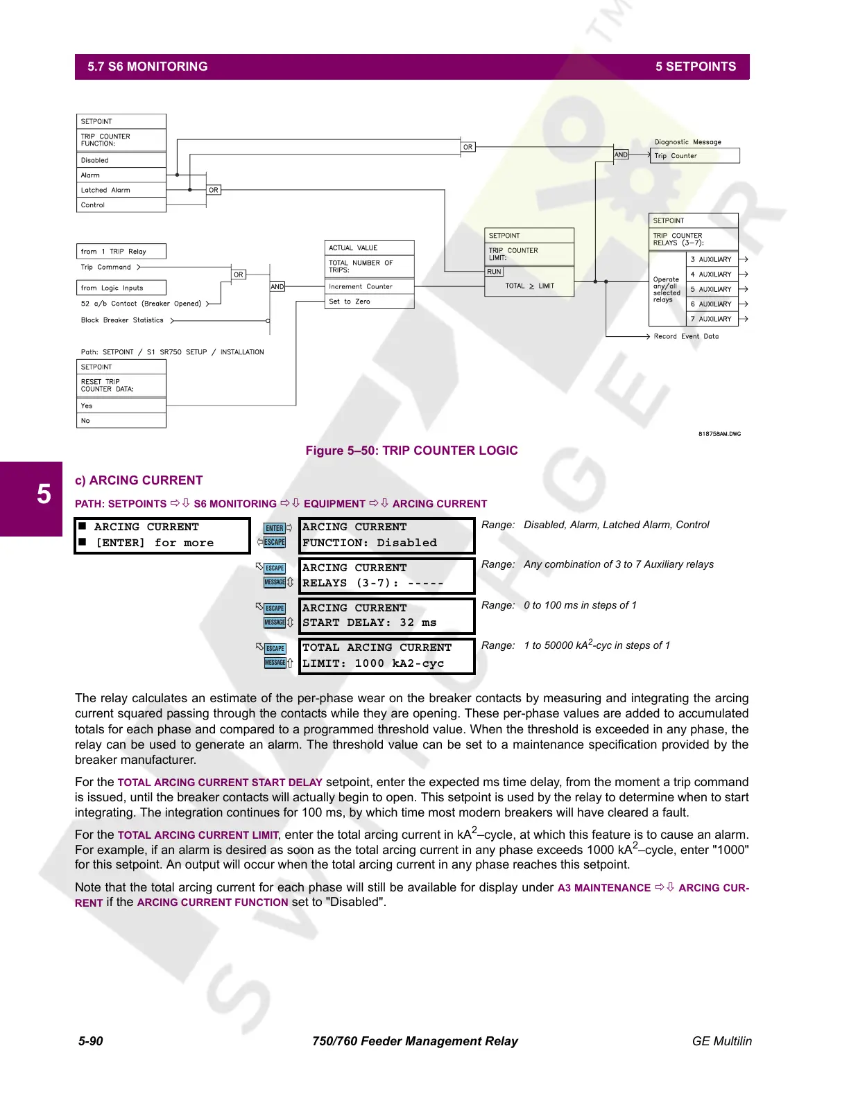
Figure 5–50: TRIP COUNTER LOGIC
c) ARCING CURRENT
PATH: SETPOINTS ÖØ S6 MONITORING ÖØ EQUIPMENT ÖØ ARCING CURRENT
The relay calculates an estimate of the per-phase wear on the breaker contacts by measuring and integrating the arcing
current squared passing through the contacts while they are opening. These per-phase values are added to accumulated
totals for each phase and compared to a programmed threshold value. When the threshold is exceeded in any phase, the
relay can be used to generate an alarm. The threshold value can be set to a maintenance specification provided by the
breaker manufacturer.
For the
TOTAL ARCING CURRENT START DELAY setpoint, enter the expected ms time delay, from the moment a trip command
is issued, until the breaker contacts will actually begin to open. This setpoint is used by the relay to determine when to start
integrating. The integration continues for 100 ms, by which time most modern breakers will have cleared a fault.
For the
TOTAL ARCING CURRENT LIMIT, enter the total arcing current in kA
2
–cycle, at which this feature is to cause an alarm.
For example, if an alarm is desired as soon as the total arcing current in any phase exceeds 1000 kA
2
–cycle, enter "1000"
for this setpoint. An output will occur when the total arcing current in any phase reaches this setpoint.
Note that the total arcing current for each phase will still be available for display under
A3 MAINTENANCE ÖØ ARCING CUR-
RENT
if the ARCING CURRENT FUNCTION set to "Disabled".
ARCING CURRENT
[ENTER] for more
ARCING CURRENT
FUNCTION: Disabled
Range: Disabled, Alarm, Latched Alarm, Control
ARCING CURRENT
RELAYS (3-7): -----
Range: Any combination of 3 to 7 Auxiliary relays
ARCING CURRENT
START DELAY: 32 ms
Range: 0 to 100 ms in steps of 1
TOTAL ARCING CURRENT
LIMIT: 1000 kA2-cyc
Range: 1 to 50000 kA
2
-cyc in steps of 1
ENTER
ESCAPE
ð
ð
MESSAGE
ESCAPE
MESSAGE
ESCAPE
MESSAGE
ESCAPE
Courtesy of NationalSwitchgear.com
 Loading...


