6-18 750/760 Feeder Management Relay GE Multilin
6.5 A4 EVENT RECORDER 6 ACTUAL VALUES
6
6.5.2 LAST RESET DATE
PATH: ACTUAL VALUES ÖØ A4 EVENT RECORDER ÖØ LAST RESET DATE
After the header message for the last event is a message indicating when the event recorder was last cleared.
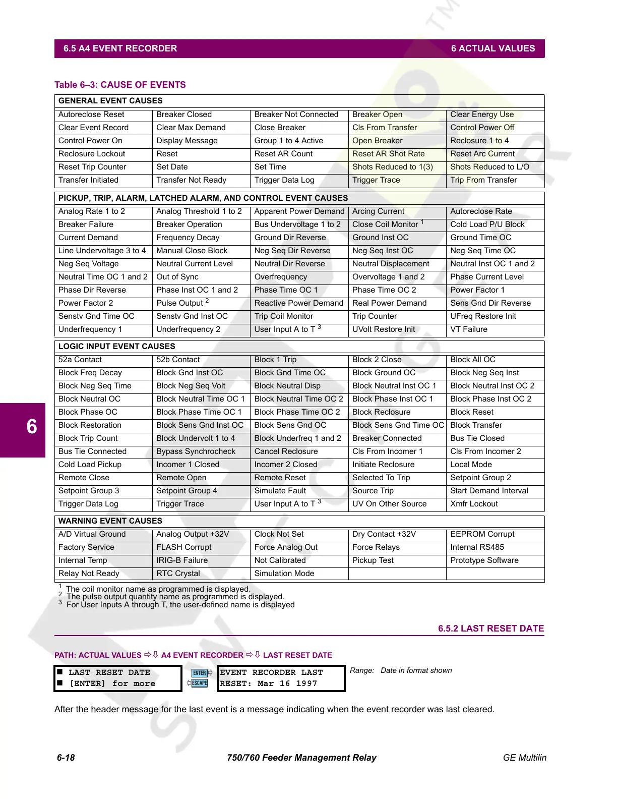
Table 6–3: CAUSE OF EVENTS
GENERAL EVENT CAUSES
Autoreclose Reset Breaker Closed Breaker Not Connected Breaker Open Clear Energy Use
Clear Event Record Clear Max Demand Close Breaker Cls From Transfer Control Power Off
Control Power On Display Message Group 1 to 4 Active Open Breaker Reclosure 1 to 4
Reclosure Lockout Reset Reset AR Count Reset AR Shot Rate Reset Arc Current
Reset Trip Counter Set Date Set Time Shots Reduced to 1(3) Shots Reduced to L/O
Transfer Initiated Transfer Not Ready Trigger Data Log Trigger Trace Trip From Transfer
PICKUP, TRIP, ALARM, LATCHED ALARM, AND CONTROL EVENT CAUSES
Analog Rate 1 to 2 Analog Threshold 1 to 2 Apparent Power Demand Arcing Current Autoreclose Rate
Breaker Failure Breaker Operation Bus Undervoltage 1 to 2 Close Coil Monitor
1
Cold Load P/U Block
Current Demand Frequency Decay Ground Dir Reverse Ground Inst OC Ground Time OC
Line Undervoltage 3 to 4 Manual Close Block Neg Seq Dir Reverse Neg Seq Inst OC Neg Seq Time OC
Neg Seq Voltage Neutral Current Level Neutral Dir Reverse Neutral Displacement Neutral Inst OC 1 and 2
Neutral Time OC 1 and 2 Out of Sync Overfrequency Overvoltage 1 and 2 Phase Current Level
Phase Dir Reverse Phase Inst OC 1 and 2 Phase Time OC 1 Phase Time OC 2 Power Factor 1
Power Factor 2 Pulse Output
2
Reactive Power Demand Real Power Demand Sens Gnd Dir Reverse
Senstv Gnd Time OC Senstv Gnd Inst OC Trip Coil Monitor Trip Counter UFreq Restore Init
Underfrequency 1 Underfrequency 2 User Input A to T
3
UVolt Restore Init VT Failure
LOGIC INPUT EVENT CAUSES
52a Contact 52b Contact Block 1 Trip Block 2 Close Block All OC
Block Freq Decay Block Gnd Inst OC Block Gnd Time OC Block Ground OC Block Neg Seq Inst
Block Neg Seq Time Block Neg Seq Volt Block Neutral Disp Block Neutral Inst OC 1 Block Neutral Inst OC 2
Block Neutral OC Block Neutral Time OC 1 Block Neutral Time OC 2 Block Phase Inst OC 1 Block Phase Inst OC 2
Block Phase OC Block Phase Time OC 1 Block Phase Time OC 2 Block Reclosure Block Reset
Block Restoration Block Sens Gnd Inst OC Block Sens Gnd OC Block Sens Gnd Time OC Block Transfer
Block Trip Count Block Undervolt 1 to 4 Block Underfreq 1 and 2 Breaker Connected Bus Tie Closed
Bus Tie Connected Bypass Synchrocheck Cancel Reclosure Cls From Incomer 1 Cls From Incomer 2
Cold Load Pickup Incomer 1 Closed Incomer 2 Closed Initiate Reclosure Local Mode
Remote Close Remote Open Remote Reset Selected To Trip Setpoint Group 2
Setpoint Group 3 Setpoint Group 4 Simulate Fault Source Trip Start Demand Interval
Trigger Data Log Trigger Trace User Input A to T
3
UV On Other Source Xmfr Lockout
WARNING EVENT CAUSES
A/D Virtual Ground Analog Output +32V Clock Not Set Dry Contact +32V EEPROM Corrupt
Factory Service FLASH Corrupt Force Analog Out Force Relays Internal RS485
Internal Temp IRIG-B Failure Not Calibrated Pickup Test Prototype Software
Relay Not Ready RTC Crystal Simulation Mode
1
The coil monitor name as programmed is displayed.
2
The pulse output quantity name as programmed is displayed.
3
For User Inputs A through T, the user-defined name is displayed
LAST RESET DATE
[ENTER] for more
EVENT RECORDER LAST
RESET: Mar 16 1997
Range: Date in format shown
ENTER
ESCAPE
ð
ð
Courtesy of NationalSwitchgear.com
 Loading...


