7-38 750/760 Feeder Management Relay GE Multilin
7.4 MODBUS MEMORY MAP 7 COMMUNICATIONS
7
1BD2
2
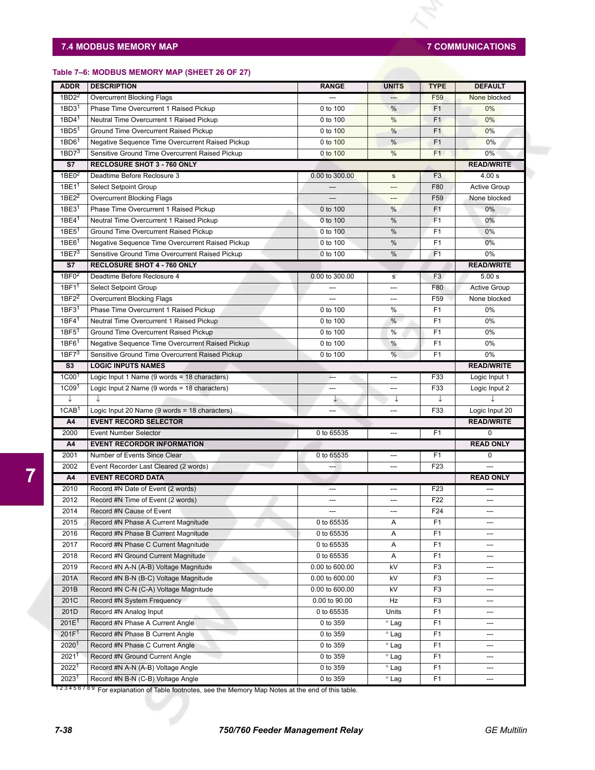
Overcurrent Blocking Flags --- --- F59 None blocked
1BD3
1
Phase Time Overcurrent 1 Raised Pickup 0 to 100 % F1 0%
1BD4
1
Neutral Time Overcurrent 1 Raised Pickup 0 to 100 % F1 0%
1BD5
1
Ground Time Overcurrent Raised Pickup 0 to 100 % F1 0%
1BD6
1
Negative Sequence Time Overcurrent Raised Pickup 0 to 100 % F1 0%
1BD7
3
Sensitive Ground Time Overcurrent Raised Pickup 0 to 100 % F1 0%
S7 RECLOSURE SHOT 3 - 760 ONLY READ/WRITE
1BE0
2
Deadtime Before Reclosure 3 0.00 to 300.00 s F3 4.00 s
1BE1
1
Select Setpoint Group --- --- F80 Active Group
1BE2
2
Overcurrent Blocking Flags --- --- F59 None blocked
1BE3
1
Phase Time Overcurrent 1 Raised Pickup 0 to 100 % F1 0%
1BE4
1
Neutral Time Overcurrent 1 Raised Pickup 0 to 100 % F1 0%
1BE5
1
Ground Time Overcurrent Raised Pickup 0 to 100 % F1 0%
1BE6
1
Negative Sequence Time Overcurrent Raised Pickup 0 to 100 % F1 0%
1BE7
3
Sensitive Ground Time Overcurrent Raised Pickup 0 to 100 % F1 0%
S7 RECLOSURE SHOT 4 - 760 ONLY READ/WRITE
1BF0
2
Deadtime Before Reclosure 4 0.00 to 300.00 s F3 5.00 s
1BF1
1
Select Setpoint Group --- --- F80 Active Group
1BF2
2
Overcurrent Blocking Flags --- --- F59 None blocked
1BF3
1
Phase Time Overcurrent 1 Raised Pickup 0 to 100 % F1 0%
1BF4
1
Neutral Time Overcurrent 1 Raised Pickup 0 to 100 % F1 0%
1BF5
1
Ground Time Overcurrent Raised Pickup 0 to 100 % F1 0%
1BF6
1
Negative Sequence Time Overcurrent Raised Pickup 0 to 100 % F1 0%
1BF7
3
Sensitive Ground Time Overcurrent Raised Pickup 0 to 100 % F1 0%
S3 LOGIC INPUTS NAMES READ/WRITE
1C00
1
Logic Input 1 Name (9 words = 18 characters) --- --- F33 Logic Input 1
1C09
1
Logic Input 2 Name (9 words = 18 characters) --- --- F33 Logic Input 2
↓↓ ↓↓↓↓
1CAB
1
Logic Input 20 Name (9 words = 18 characters) --- --- F33 Logic Input 20
A4 EVENT RECORD SELECTOR READ/WRITE
2000 Event Number Selector 0 to 65535 --- F1 0
A4 EVENT RECORDOR INFORMATION READ ONLY
2001 Number of Events Since Clear 0 to 65535 --- F1 0
2002 Event Recorder Last Cleared (2 words) --- --- F23 ---
A4 EVENT RECORD DATA READ ONLY
2010 Record #N Date of Event (2 words) --- --- F23 ---
2012 Record #N Time of Event (2 words) --- --- F22 ---
2014 Record #N Cause of Event --- --- F24 ---
2015 Record #N Phase A Current Magnitude 0 to 65535 A F1 ---
2016 Record #N Phase B Current Magnitude 0 to 65535 A F1 ---
2017 Record #N Phase C Current Magnitude 0 to 65535 A F1 ---
2018 Record #N Ground Current Magnitude 0 to 65535 A F1 ---
2019 Record #N A-N (A-B) Voltage Magnitude 0.00 to 600.00 kV F3 ---
201A Record #N B-N (B-C) Voltage Magnitude 0.00 to 600.00 kV F3 ---
201B Record #N C-N (C-A) Voltage Magnitude 0.00 to 600.00 kV F3 ---
201C Record #N System Frequency 0.00 to 90.00 Hz F3 ---
201D Record #N Analog Input 0 to 65535 Units F1 ---
201E
1
Record #N Phase A Current Angle 0 to 359 ° Lag F1 ---
201F
1
Record #N Phase B Current Angle 0 to 359 ° Lag F1 ---
2020
1
Record #N Phase C Current Angle 0 to 359 ° Lag F1 ---
2021
1
Record #N Ground Current Angle 0 to 359 ° Lag F1 ---
2022
1
Record #N A-N (A-B) Voltage Angle 0 to 359 ° Lag F1 ---
2023
1
Record #N B-N (C-B) Voltage Angle 0 to 359 ° Lag F1 ---
Table 7–6: MODBUS MEMORY MAP (SHEET 26 OF 27)
ADDR DESCRIPTION RANGE UNITS TYPE DEFAULT
1 2 3 4 5 6 7 8 9
For explanation of Table footnotes, see the Memory Map Notes at the end of this table.
Courtesy of NationalSwitchgear.com
 Loading...


