7-48 750/760 Feeder Management Relay GE Multilin
7.4 MODBUS MEMORY MAP 7 COMMUNICATIONS
7
Data Formats Notes:
1 New for version 2.10
2 Changed from version 2.00 to 2.10
3 New or have changed for version 3.00
4 New or have changed for version 3.20
5 New for version 3.30
6 New for version 3.31 MOD 010
7 New or have changed for version 3.60
8 New or have changed for version 3.70
9 New or have changed for version 4.00
F86
1
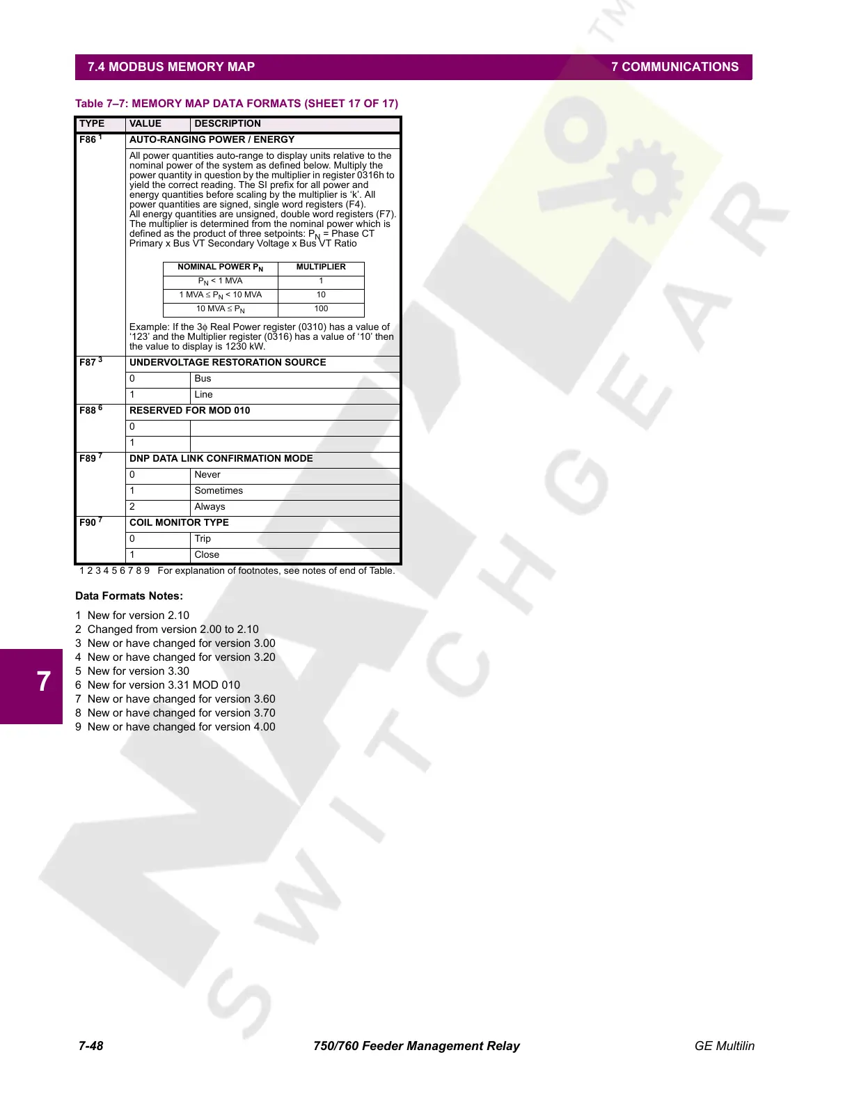
AUTO-RANGING POWER / ENERGY
All power quantities auto-range to display units relative to the
nominal power of the system as defined below. Multiply the
power quantity in question by the multiplier in register 0316h to
yield the correct reading. The SI prefix for all power and
energy quantities before scaling by the multiplier is ‘k’. All
power quantities are signed, single word registers (F4).
All energy quantities are unsigned, double word registers (F7).
The multiplier is determined from the nominal power which is
defined as the product of three setpoints: P
N
= Phase CT
Primary x Bus VT Secondary Voltage x Bus VT Ratio
Example: If the 3φ Real Power register (0310) has a value of
‘123’ and the Multiplier register (0316) has a value of ‘10’ then
the value to display is 1230 kW.
F87
3
UNDERVOLTAGE RESTORATION SOURCE
0Bus
1Line
F88
6
RESERVED FOR MOD 010
0
1
F89
7
DNP DATA LINK CONFIRMATION MODE
0 Never
1 Sometimes
2Always
F90
7
COIL MONITOR TYPE
0Trip
1 Close
Table 7–7: MEMORY MAP DATA FORMATS (SHEET 17 OF 17)
TYPE VALUE DESCRIPTION
1 2 3 4 5 6 7 8 9 For explanation of footnotes, see notes of end of Table.
NOMINAL POWER P
N
MULTIPLIER
P
N
< 1 MVA 1
1 MVA ≤ P
N
< 10 MVA 10
10 MVA ≤ P
N
100
Courtesy of NationalSwitchgear.com
 Loading...


