GE Multilin 750/760 Feeder Management Relay 8-19
8 COMMISSIONING TESTS 8.4 PROTECTION SCHEMES
8
4. Slowly reduce the Phase A current until the Pickup LED goes out and note the dropout level, which should be 2% of
CT less than pickup when pickup ≤ CT, or 97 to 98% of pickup when pickup > CT.
5. Repeat Steps 1 through 4 for current at 150% in Phases C and A and adjusted in B.
6. Repeat Steps 1 through 4 for current at 150% in Phases B and A and adjusted in C.
The following procedure checks the blocking from logic inputs:
1. Inject current into the required number of phases to cause a pickup.
2. Assert a logic input to provide a "Block Phase Inst 1". The Pickup LED should immediately go out.
3. Repeat Steps 1 and 2 for logic inputs "Block Phase O/C", "Block All O/C" and “Block 1 Trip Relay” as required.
The following procedure checks Phase IOC 1 timing:
1. Connect the Stop Trigger to the interval timer.
2. Preset the current source to a minimum of 110% of pickup current, then turn the current off and reset the timer.
3. Inject the preset current into the required number of phases and note the delay time, then reset the timer.
4. Repeat Step 3 four more times and obtain an average of the time intervals.
5. Reset the relay and disconnect the “Stop Trigger.”
d) PHASE IOC 2
The procedures to test this element are identical to those outlined for Phase IOC 1 above, with the exception of the block-
ing from logic inputs check, which is performed as follows:
1. Inject current into the required number of phases to cause a pickup.
2. Assert a logic input to provide a "Block Phase Inst 2" and verify the Pickup LED immediately turns off.
3. Repeat Steps 1 and 2 for logic inputs "Block Phase O/C", "Block All O/C" and “Block 1 TRIP Relay” as required.
e) PHASE DIRECTIONAL OC
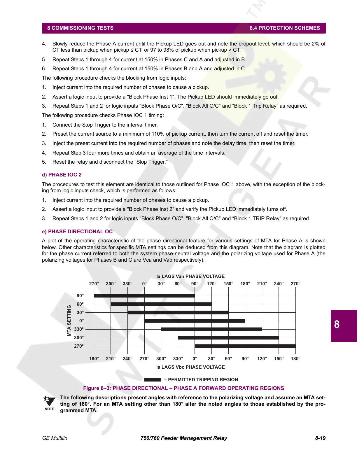
A plot of the operating characteristic of the phase directional feature for various settings of MTA for Phase A is shown
below. Other characteristics for specific MTA settings can be deduced from this diagram. Note that the diagram is plotted
for the phase current referred to both the system phase-neutral voltage and the polarizing voltage used for Phase A (the
polarizing voltages for Phases B and C are Vca and Vab respectively).
Figure 8–3: PHASE DIRECTIONAL – PHASE A FORWARD OPERATING REGIONS
The following descriptions present angles with reference to the polarizing voltage and assume an MTA set-
ting of 180°. For an MTA setting other than 180° alter the noted angles to those established by the pro-
grammed MTA.
Ia LAGS Van PHASE VOLTAGE
300° 330° 0° 30° 60°
90°
120° 150°
180°
210° 240° 270°270°
0° 30° 60°
90°
120° 150°
180°
300° 330°270°
180°
210° 240°
Ia LAGS Vbc PHASE VOLTAGE
MTA SETTING
270°
300°
330°
0°
30°
60°
90°
= PERMITTED TRIPPING REGION
NOTE
Courtesy of NationalSwitchgear.com
 Loading...


