GE Multilin 750/760 Feeder Management Relay 8-57
8 COMMISSIONING TESTS 8.7 PLACING THE RELAY IN SERVICE
8
10. Under subheading A2 METERING ÖØ DMND ÖØ REACTIVE PWR, verify the LAST REACTIVE PWR DMND and MAX REACTIVE
PWR DMND values.
11. Under subheading A2 METERING ÖØ DMND ÖØ APPARENT PWR, verify the LAST APPARENT PWR DMND and MAX APPAR-
ENT PWR DMND values.
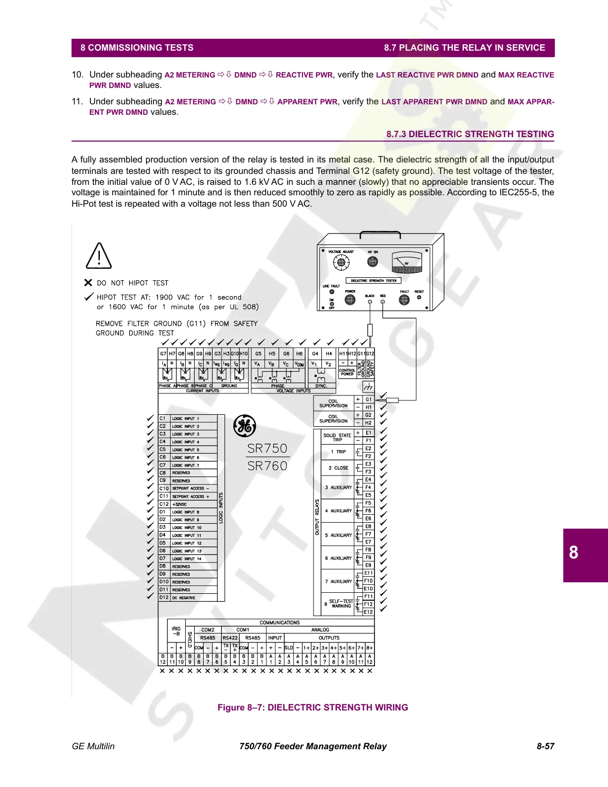
8.7.3 DIELECTRIC STRENGTH TESTING
A fully assembled production version of the relay is tested in its metal case. The dielectric strength of all the input/output
terminals are tested with respect to its grounded chassis and Terminal G12 (safety ground). The test voltage of the tester,
from the initial value of 0 V AC, is raised to 1.6 kV AC in such a manner (slowly) that no appreciable transients occur. The
voltage is maintained for 1 minute and is then reduced smoothly to zero as rapidly as possible. According to IEC255-5, the
Hi-Pot test is repeated with a voltage not less than 500 V AC.
Figure 8–7: DIELECTRIC STRENGTH WIRING
Courtesy of NationalSwitchgear.com
 Loading...


