An active window pops up:
BACK
CH1
A
OFFSET X
CTL
EIN
+125%
–050%
INC
RES
DEC
+050%
+030%
CH3
>>
AKT
ON
B
OFFSET Y
SYM
OFF
SERVO
PHASE 1 Prog.MIX
TRIM
ON
Select
CLR
NO
LOGIC
Assign a switch or control switch as described in sec-
tion Control and Switch Assignment (page 26).
Press the BACK button at the top left of the display
to return to the mixer selection.
Curve (6 to 8) Mixer Setup
These three curve mixers make it possible to define
extremely nonlinear mixer guide lines with up to five
freely positionable points between the two endpoints
along the control travel: L (low = -100% control travel)
and H (high = +100% control travel) .
Programming Details
The control curve can be specified by up to 7 points,
(termed “support points”) along the entire control stick
travel. In the basic program setting, 2 support points
describe a linear characteristic; the two endpoints at
the bottom control stick stop L and at the top control
stick stop H.
Notice
The following examples are for demonstration
purposes only and do not represent a realistic
mixer guide line.
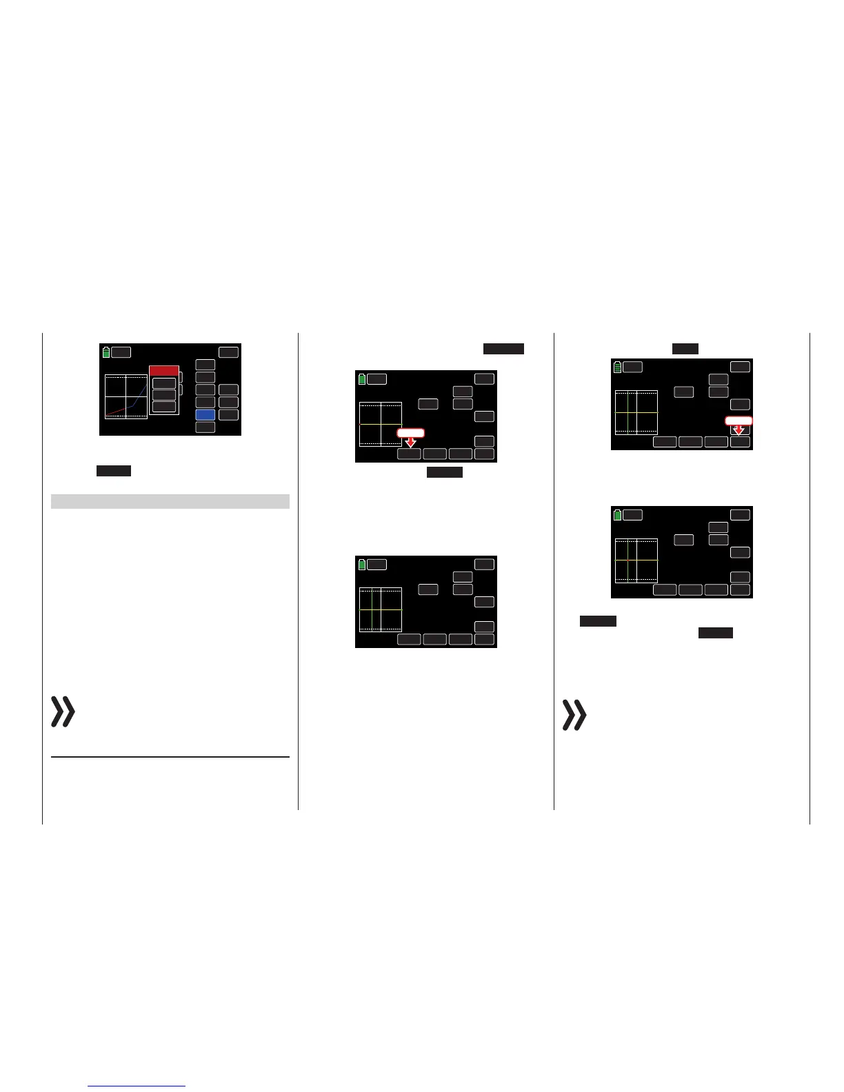
Setting Support Points
A green vertical line, normally hidden, appears and
movessynchronously in the graphic between the two
mixer input control endpoints once the control switch
is activated. (In the example below, control function
CH8 is assigned to theside proportionalrotary control
SL1.) To show the green line, press the ST OFF but-
ton at the bottom left to activate the switch:
BACK
PHASE 1
IN
OUT
POINT
ON
INC
ENT
DEC
Y-axis
X-axis
ST OFF
ACT
–100%
000%
000%
L
SERVO
Prog.MIX
ON
CTL
CH8 >> CH10
TRIM
ON
Press
The value field changes to ST ON, the green vertical
line representing the temporary control position ap-
pears in the graph and the control position is numeri-
cally displayed in the input IN line.
In the example below, the control at input CH8 is at
-045% of the control travel. The output signal remains
000% since a value has not been entered:
BACK
PHASE 1
IN
OUT
POINT
ON
INC
ENT
DEC
Y-axis
X-axis
ST ON
ACT
000%
000%
?
SERVO
Prog.MIX
ON
CTL
CH8 >> CH10
–045%
TRIM
ON
The intersection of this line with the mixer curve is
identified as output in the OUT line and can be var-
ied at the support points within a range of ± 125%.
This alters the control signal which affects the mixer
output.
Up to five additional support points can be set be-
tween the L and H endpoints; the distance between
each support points must be a minimum of 25%.
Move the green line via the related control. To set a
support point, press the ENT button:
BACK
PHASE 1
IN
OUT
POINT
ON
INC
ENT
DEC
Y-axis
X-axis
ST ON
ACT
000%
000%
?
SERVO
Prog.MIX
ON
CTL
CH8 >> CH10
–045%
TRIM
ON
Press
A red dot appears at the intersection between the two
lines. At the same time, the ? in the POINT line is re-
placed with a point number, and the value field to the
right shows the current output value:
BACK
PHASE 1
IN
OUT
POINT
ON
INC
ENT
DEC
Y-axis
X-axis
ST ON
ACT
000%
000%
1
SERVO
Prog.MIX
ON
CTL
CH8 >> CH10
–045%
TRIM
ON
The set point can be moved horizontally with
the X-axis function within a range of approximately
± 90%, and vertically with the Y-axis function within
a range of ±125%. Refer to the Changing the Sup-
port Point Value section (page 140) for additional in-
formation.
Notice
Remember that the percentages in the input (IN)
and output (OUT) line always refer to the tempo-
rary position of the control stick and not to the
position of the point.
Use the same procedure to set the other support
points. The 5 support points between the L and H
endpoints can be created in any order; support points
139
Function menu | general - Free mixer

 Loading...


