WIZ.
CH
D/R
EXP
CTL
ROLL
+100%
+100%
NULL
INC
RES
DEC
PHASE 1
000%
000%
SYM
OFF
D/R,EXP
Press
Press the INC button at the right edge of the display
to increase the value of the active option field. Press
the DEC button to reduce the value of the active op-
tion field. Press the RES button to reset the changed
value back to the default. Alternatively, press the ar-
row keys ( pq ) to the left of the display screen to
achieve the same increase/decrease result.
The adjustment range is ±125 % in the D/R line and
±100 % in the EXP line.
To switch between two variants, assign a switch or a
control in the CTL line. Refer the Control and Switch
Assignment section (page 26) for more information.
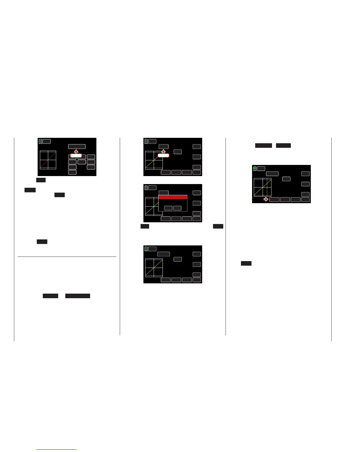
Press the WIZ. button to bring up the PIT.CRV dis-
play:
PIT.CRV (Pitch Curve)
Use the Pitch min line to adjust the movement di-
rection of the pitch stick. The remaining options will
adjust the pitch curve.
1. Stick Direction
To reverse the control direction of the pitch con-
trol stick from the standard pre-set position "pitch
min back" to "pitch min forward", and vice versa,
press the BACK or FORWARD button in the
"Pitch min" line:
WIZ.
NORMAL
IN
OUT
POINT
OFF
INC
ENT
DEC
Y-axis
TRIM
X-axis
ST OFF
Curve
–100%
–100%
–100%
L
PIT.CRV
Pitch min.
BACK
Press
Pressing the button will bring up an active warning:
WIZ.
NORMAL
EIN
AUS
POINT
AUS
INC
ENT
DEC
Y-axis
TRIM
X-axis
ST OFF
KURVE
–100%
–100%
–100%
L
PIT.CRV
Pitch min.
BACK
YES
NO
SURE?
Warning
Press NO to terminate the procedure. Press YES
to confirm the procedure and reverse the move-
ment direction of the pitch stick WITHOUT any vi-
sual changes in the display:
WIZ.
NORMAL
IN
OUT
POINT
OFF
INC
ENT
DEC
Y-axis
TRIM
X-axis
ST OFF
Curve
–100%
–100%
–100%
L
PIT.CRV
Pitch min.
FORWARD
2. Pitch Curve Settings
Tip
These options and settings can be changed via the
FUNCTION submenu PHASE (page 120).
Basic Operating Steps
• Button ST OFF / ST ON
Press this button to turn the graphic and nu-
meric display of the control stick position on
and off, as shown below:
WIZ.
IN
OUT
POINT
OFF
INC
ENT
DEC
Y-axis
TRIM
X-axis
ST ON
Curve
+050%
+050%
000%
?
Pitch min.
FORWARD
NORMAL
PIT.CRV
With the control element (gas/pitch control
stick), a vertical green line is moved synchro-
nously in the graph between the two endpoints
"L" and "H". The momentary control stick po-
sition (input) is displayed numerically in the IN
line (-100 % to +100 %). The intersection of this
line with the curve (output) is displayed numer-
ically in the OUT line and can be varied at the
support points between -125% and +125%. A
control signal changed in this way affects all of
the following mixing and coupling functions:
• ENT Button
Press the button at the bottom right of the dis-
play to set up to 5 additional points between
the two endpoints "L" and "H".
In the following example, the control stick is ex-
actly between the middle and end of its path,
at +50% of the control path, and generates an
output signal that is also +50% due to the lin-
ear characteristic.
48 Base menu - Model selection

 Loading...


