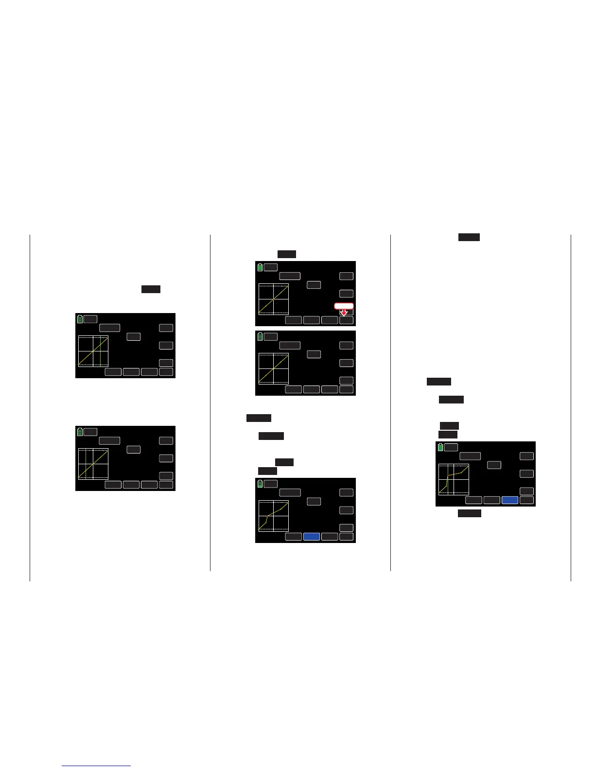
Once the support point number and value ap-
pear in the POINT line, delete the point by
touching the ENT button, as shown below:
NORMAL
PIT.CRV
WIZ.
IN
OUT
POINT
OFF
INC
ENT
DEC
Y-axis
TRIM
X-axis
ST ON
Curve
000%
000%
000%
2
Pitch min.
FORWARD
Press
NORMAL
PIT.CRV
WIZ.
IN
OUT
POINT
OFF
INC
ENT
DEC
Y-axis
TRIM
X-axis
ST ON
Curve
000%
000%
000%
?
Pitch min.
FORWARD
Changing the Support Point Value
• X-axis Button (X-axis)
To activate this function, press to highlight
the X-axis button at the bottom of the dis-
play.
Move the selected (red) point to the right
with the INC button, and to the left with
the DEC button, as shown below:
NORMAL
PIT.CRV
WIZ.
IN
OUT
POINT
OFF
INC
ENT
DEC
Y-axis
TRIM
X-axis
ST ON
Curve
000%
000%
000%
2
Pitch min.
FORWARD
Press the X-axis button again to deactivate
the function and save the setting.
Tips
• If you move the red pointhorizontally away
from thecurrentcontrol position, the point
becomesgreen after a short while, and a
"?" appears in the POINT line. This ques-
tion mark does not relate to the point which
has been moved but rather indicates that
another point can be set at the current
control position.
• Remember that the input/output percent-
ages in the IN and OUT lines always refer
to the momentary position of the control
stick and not to the position of the point.
• Y-axis Button (Y-axis)
To activate this function, press to highlight
the Y-axis button at the bottom of the dis-
play.
Move the selected (red) point to the top with
the INC button, and to the bottom with
the DEC button, as shown below:
NORMAL
PIT.CRV
WIZ.
IN
OUT
POINT
OFF
INC
ENT
DEC
Y-axis
TRIM
X-axis
ST ON
Curve
2
–044%
+027%
+044%
Pitch min.
FORWARD
Press the Y-axis button again to deactivate
the function and save the setting.
Between the two endpoints "L" and "H", up to
5 additional support points can be set, and the
distance between neighboring support points
may not be less than approximately 25%.
Move the control stick. As long as a "?" is next
to the POINT line, you can set the next sup-
port point by touching the ENT button. Once
a POINT value is entered, the "?" is replaced
with a number:
NORMAL
PIT.CRV
WIZ.
ON
OUT
POINT
OFF
INC
ENT
DEC
Y-axis
TRIM
X-axis
ST ON
Curve
+050%
+050%
+050%
1
Pitch min.
FORWARD
The support points can be entered in any order
between the "L" and "H" endpoints; they will be
automatically renumbered sequentially from left
to right after each point is set, as shown in the
example below:
NORMAL
PIT.CRV
WIZ.
IN
OUT
POINT
OFF
INC
ENT
DEC
Y-axis
TRIM
X-axis
ST ON
Curve
–050%
–050%
–050%
1
Pitch min.
FORWARD
Deleting a Support Point
In order to delete the set support points 1 to
5, use the control stick to move the vertical
line next to the point to be deleted. Selected
points will turn red.
49
Base menu - Model selection

 Loading...


