Press the WIZ. button to return to the Pitch Curve
display:
WIZ.
CTL
SL 1
INC
RES
DEC
MIXER
THR.CRV
POINT PHASE
3
3
NONE
NONE
L
1
NONE
NONE
L
1
NONE
NONE
L
1
NONE
NONE
L
1
NONE
NONE
L
1
Press
Press the WIZ. button again to advance to the Throt-
tle Curve display:
NORMAL
PIT.CRV
WIZ.
IN
OUT
POINT
ON
INC
ENT
DEC
Y-axis
TRIM
X-axis
ST ON
Curve
2
–044%
+027%
+044%
Pitch min.
FORWARD
Press
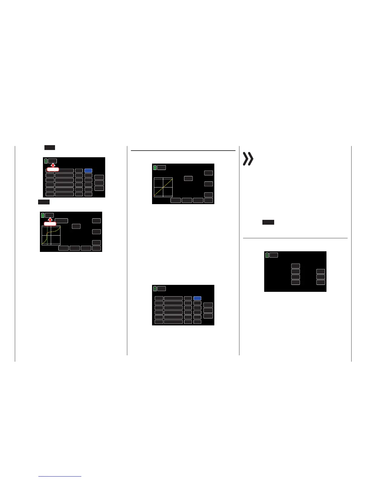
THR.CRV (Throttle Curve)
The throttle curve can be specified by assigning up to
7 support points, along the entire control stick travel:
WIZ.
NORMAL
IN
OUT
POINT
OFF
INC
ENT
DEC
Y-axis
TRIM
X-axis
ST OFF
Curve
–100%
–100%
–100%
L
THR.CRV
THR.Limit OFF
Support points can be set, changed and deleted in
the same manner as described in the previous Pitch
Curve section. First specify the throttle curve using
three points: the two end points "L" and "H", in addi-
tion to the set point "1" in the control center. These
three points harmonize the motor performance curve
with the pitch curve.
Tip
The value shown to the right of the THR.Limit line indi-
cates the status or the position of the throttle limit.
Refer to the FUNCTION submenu THR.CRV section
(page 160) for additional information about setting
throttle curves.
WIZ.
CTL
SL 1
INC
RES
DEC
MIXER
THR.CRV
POINT PHASE
3
3
NONE
NONE
L
1
NONE
NONE
L
1
NONE
NONE
L
1
NONE
NONE
L
1
NONE
NONE
L
1
Notice
The associated controller does not have any ef-
fect ifan undefined point is selected (in the basic
version of the relevant curve mixers, only the
points "L" and "H" are set).
Tips
These options and settings directly affect the TRIM
display options found in the FUNCTION submenu
PIT.CRV (page 154).
These options, settings and phase-specific throttle
curve functions can be changed via the FUNCTION
submenu PHASE (page 120).
Press the WIZ. button again to advance to the Gyro/
Governor display:
Gyr/Gover (Gyro/Governor)
Initial basic settings are needed for the gyro and/or
any governor used in the model.
WIZ.
NORMAL
Gyro Gain
000%
Gyro Suppression
Governor RATE
Governor ACT
000%
INH
050%
RES
DEC
INC
Gyr/Gover
Tip
These options, settings and phase-specific values can
be changed via the FUNCTION submenu PHASE (page
120).
52 Base menu - Model selection

 Loading...


