• Gyro Suppression Line
Notice
This option may not function with current
standard gyro systems and render the heli-
copter impossible to fly. Consult the gyro set-
ting instructions for compatibility.
This option can influence the effect of the gyro
sensor (gyroscope) as the tail rotor control stick
is moved, assuming that a gyro system is used in
which the gyro's effect can be set by the trans-
mitter using an additional channel (CH 7 in the
Graupner remote-control system). The gyro sup-
pression reduces the gyro's effect in a linear man-
ner in proportion to the deflection of the tail rotor
control stick corresponding to the set value. If the
gyro has not been suppressed (at a value of 0%),
the gyro's effect remains independent of the con-
trol stick deflection.
However, the gyro's effect can be varied smooth-
ly between a minimum and maximum using a con-
trol assigned in the Gyro line in the BASE submenu
CTL Set (for example with one of the proportion-
al dials DVx). For more information refer to the
Gyro/Governor section (page 166).
• Gyro Gain Line
Most of the current gyro systems can be adjusted
for a smooth, proportional effect; the transmitter
allows for a choice between two different modes
of action.
If the gyro being used has one of these options,
the alternative offset setting enables both the nor-
mal gyro gain and "heading lock mode" as well as
flying with maximum stabilization in normal, slow
fights within this selected mode, and reducing the
gyro gain in fast roundtrips and aerobatics.
Values up to ±125% are possible, as shown below:
WIZ.
NORMAL
Gyro Gain
000%
Gyro Suppression
Governor RATE
Governor ACT
+023%
INH
050%
RES
DEC
INC
Gyr/Gover
Based on these phase specific settings (offset) the
gyro gain can also be proportionally varied with a
control assigned in the CH 7 line in the BASE sub-
menu CTL Set, (for example the proportional dial
DVx).
Attention
• This option maynot function with current
standard gyro systems and render the he-
licopter impossible to fly. Consult the gyro
setting instructions for compatibility.
• Note that the offset values enteredin this
option as well as in the CH 7 line of the
BASE sub-menu CTL Set must add up!
For ease of use, make sure to only enter
or change an offset value in one of the two
options.
• Governor ACT Line
In contrast to speed controllers that only regulate
performance like a carburetor, governors maintain
a constant speed in the system they are monitor-
ing by independently regulating the provided out-
put. Like cruise control in cars, in an ICE helicopter
a governor controls the throttle servo in the same
way as the speed controller of an electric motor he-
licopter. Governors therefore only require a speed
setting and not a classic throttle curve. A deviation
from the set speed occurs when the required out-
put exceeds the maximum available output.
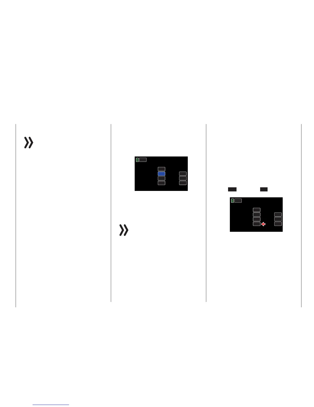
To change the current value, touch the desired but-
ton in the Governor ACR line. The display switch-
es from INH (inhibit/off) to ON and vice versa, as
shown below:
WIZ.
NORMAL
Gyro Gain
000%
Gyro Suppression
Governor RATE
Governor ACT
+023%
ON
050%
RES
DEC
INC
Gyr/Gover
• Governor RATE Line
In the BASE submenu CTL Set GOVERNOR line,
if the function Governor at CH8 is switched on: in
the Governor RATE line, enter the appropriate off-
set value for the desired rotor speed. The value to
be set depends on the governor that is used as
well as the desired target speed, and can of course
be varied for specific phases, for example:
53
Base menu - Model selection

 Loading...


