4
Applicator description Operating instructions HERMA 400
32/154 3.28 US (130519)
Changing parts
Risk of electric shock! Disconnect all sources of supply and wait for five
minutes before opening the rear cover or touching the connector pins!
Electrocution may occur.
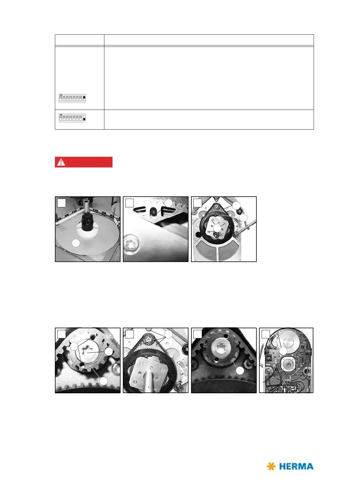
If you need to replace parts proceed as follows:
> Remove the take-up disk 1.
> Lock the unit by placing a pin into hole 2 (fi
g. B).
> Loosen (do not remove) screws 3 (fi
g. C).
> Turn the shaft to the left. You may then remove toothed belt disk 4 and
belt 5.
If you also need to replace the circuit board you have to remove the motor first:
> Gear 6
is accessible (fig. D). Place two Allen screws M3x5 (DIN912) into holes 7 (functions as
pulling-off device). Remove torx screw 8 (you have to overcome a certain resistance). Make sure to
hold the motor at the same time. Gear 6 can be removed.
> Remove screws 9 (fi
g. E) while holding the motor.
Switch 8 Determines the pre-set sense of rotation of the unit, seen fro the front side
of
the unit, facing to the disc / the roller
(Motorised unwinder: any change is to be effected with the illuminated
button).
Motorised rewinder: See the note below
On: Clockwise (choose this setting with unwinder / rewinder variant R, with loop
unit and with magazine filler variant L)
Off: Counterclockwise (choose this setting with unwinder / rewinder variant L,
with loop unit and with magazine filler variant R)
DIP switch Configuration