4
Applicator description
Operating instructions HERMA 400
38/154 3.28 US (130519)
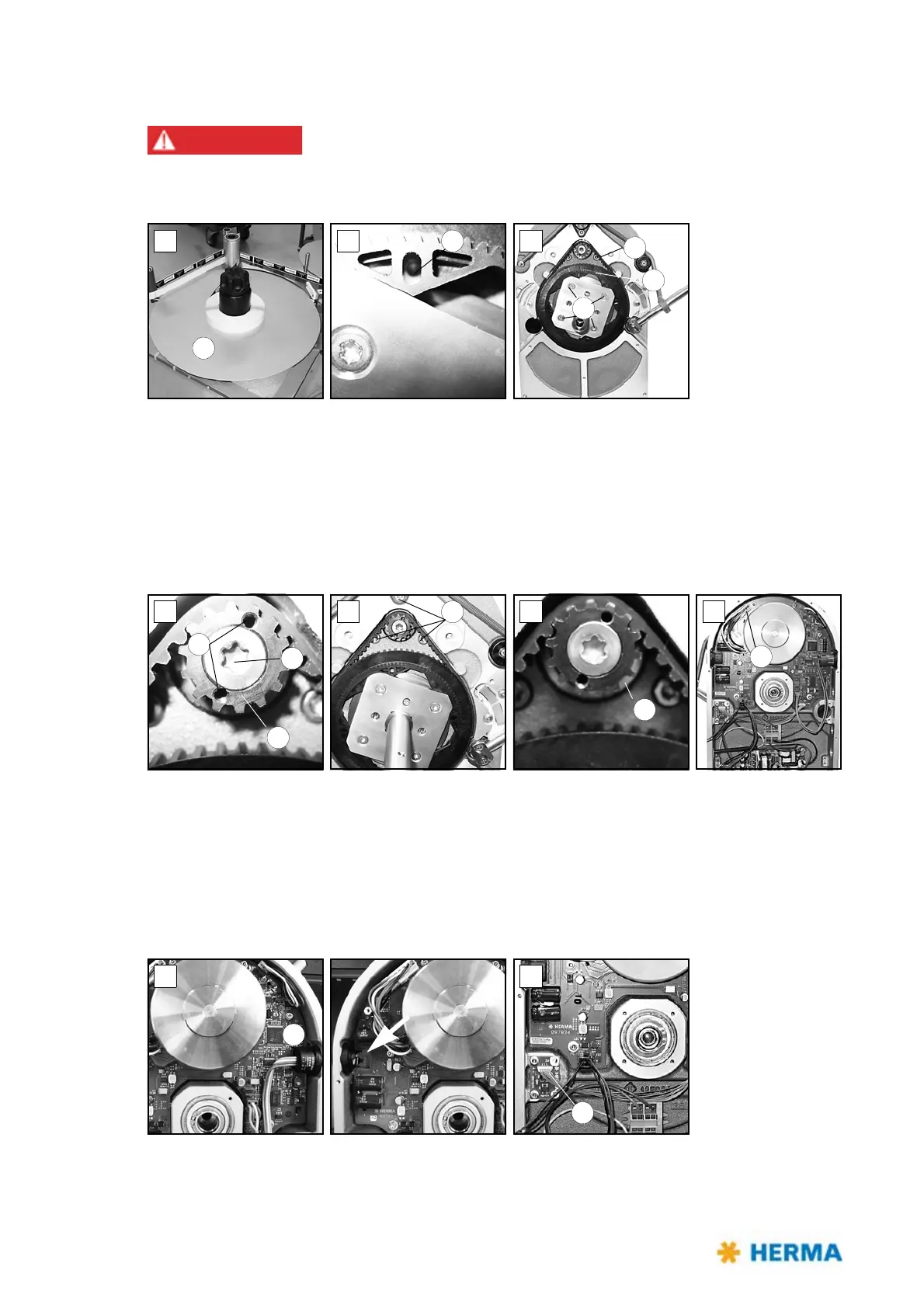
Changing parts
Risk of electric shock! Disconnect all sources of supply and wait for five
minutes before opening the rear cover or touching the connector pins!
Electrocution may occur.
If you need to replace parts proceed as follows:
> Remove the take-up disk 1.
> Lock the unit by placing a pin into hole 2 (fig. B).
> Loosen (do not remove) screws 3 (fig. C).
> Turn the shaft to the left. You may then remove toothed belt disk 4 and belt 5.
If you also need to replace the circuit board you have to remove the motor first:
> Gear 6 is accessible (fig. D). Place two Allen screws M3x5 (DIN912) into holes 7 (functions as
pulling-off device). Remove torx screw 8 (you have to overcome a certain resistance). Make sure to
hold the motor at the same time. Gear 6 can be removed.
> Remove screws 9 (fig. E) while holding the motor.
> Remove disk 10 (fig. F). The motor is now held only by plug 11 (fig. G). Loosen the plug and remove
the motor.
> The circuit board can be removed carefully. To do so first lift it at the side opposite to button 12
(fig. H).