4
Operating instructions
HERMA 400 APPLICATOR DESCRIPTION
3.28 US (130519) 67/154
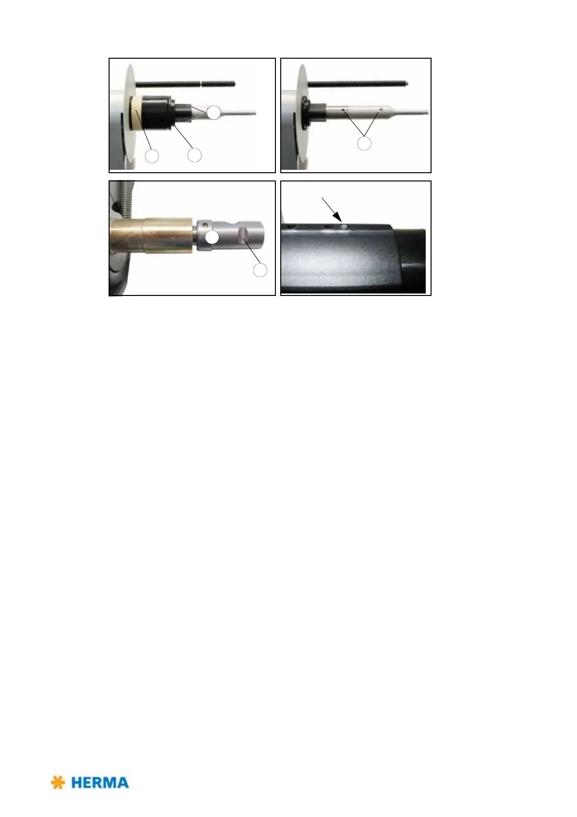
When remounting the core sleeve in reverse order with the new tension rings make sure that the
screws (12, 14) together with the plug-in parts 15 (with pins) are aligned exactly onto the respective
holes 16.
Moreover, screw 14 (the one closer to the disk) must be aligned exactly onto flat surface b on clamping
piece 17.
After assembling the unit completely the screws (12, 14) must be flush with the sleeves.
Important: Pins a (three per plug-in part) are absolutely required for a proper function.
Verify correct function / reliable clamping of the rewinder after complete assembly.