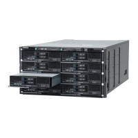
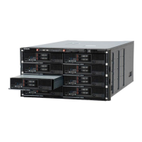
Figure 5-94 Removing the connection kit F/H
Installing a connection kit F/H
1. Put on an anti-static wrist strap.
2. If the connector cover is installed in the mezzanine slot #2, remove it
from the slot.
Figure 5-95 Removing the connector cover
3. Align the connector and guide holes of the connection board of the
connection kit F/H with the male connector and guide pins on the main
board of the server blade, respectively.
4. Push in the connection board into the server blade straight downward by
pushing the portion indicated Push, and then close the two latches.
5. Push in the connector into the PCI expansion blade straight downward by
pushing the portion indicated Push, and then close the latch.
5-76
Replacing parts
Hitachi Compute Blade 500 Series System Service Manual

 Loading...
