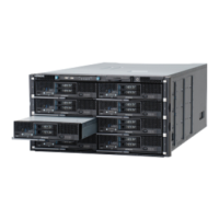
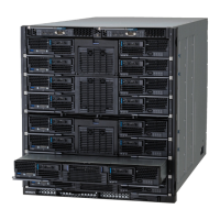
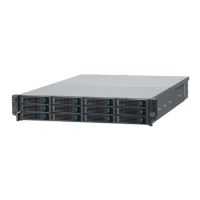
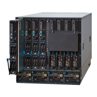
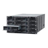
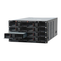
Table 1-34 LEDs and connectors on 1Gb LAN switch module
No. Name State Description
1 LAN ports 1 to 4 Green-On Link is established
Green-Blink Link activity. Port is sending or receiving data.
Amber-On Link failed.
2 Memory card slot (MC) - Slot for SD memory card.
3 Access LED (ACC) Green-On The SD memory card is accessed
4 Reset switch (RST) - Press and hold it for five seconds or more,
reset the module.
5 Power LED (PWR) Green-On Power-on and normal operation.
Off The power fails or no power supplied.
6 Status1 LED (ST1) Green-On Normal operation.
Green-Blink During power-on diagnosis or booting
software.
Red-Blink The over temperature threshold or any
warning conditions.
Red-On A serious error is detected
7 Identify LED (LOCID) Blue-On The switch module is identified.
Off The switch module is not identified
1Gb LAN switch module (40 ports)
Figure 1-43 1Gb LAN switch module
Table 1-35 LEDs and connectors on 1Gb LAN switch module
No. Name State Description
1 LAN ports 1 to 8 Green-On Link is established.
Green-Blink Link activity. Port is sending or receiving data.
Amber-On Link failed.
2 Memory Card slot (MC) - Slot for an SD memory card.
3 Access LED (ACC) Green-On The SD memory card is accessed.
1-32
Introduction
Hitachi Compute Blade 500 Series System Service Manual

 Loading...
