See How to verify the SFP function on page 5-116 section.
5. Turn off the maintenance mode from web console.
See Maintenance mode on/off procedure on page 4-10 section.
6. Verify that the replacement was successful through the MAR log.
See
Alert information identification procedure on page 4-5 section.
7. Turn off LID LED for identifying the target module.
See Identify LED (LID) on/off procedure on page 4-7 section.
SFP+ module for 16Gb FC switch
1. Put on an anti-static wrist strap.
2. If the dust cap is put in the spare SFP+ module, remove it first.
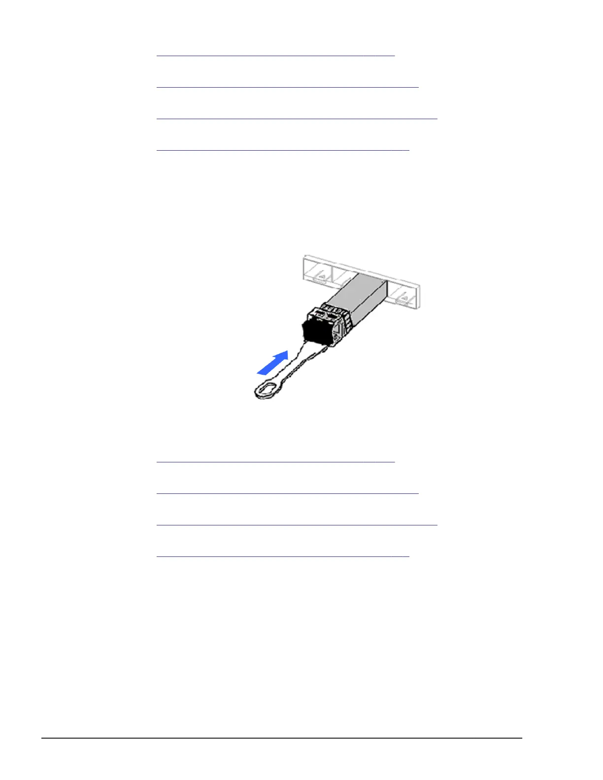
3. Insert the optical module (SFP+), and then push it into the arrowed
direction as shown in the following figure.
Figure 5-148 Installing an SFP+ module in 16Gb FC switch
4. Verify that the replaced SFP is running normally.
See How to verify the SFP function on page 5-116 section.
5. Turn off the maintenance mode from web console.
See
Maintenance mode on/off procedure on page 4-10 section.
6. Verify that the replacement was successful through the MAR log.
See
Alert information identification procedure on page 4-5 section.
7. Turn off LID LED for identifying the target module.
See Identify LED (LID) on/off procedure on page 4-7 section.
How to verify the SFP function
1. Connect the terminal software to check the SFP function.
2. Click Start > Programs > Accessories > Communications >
HyperTerminal to boot up terminal software.
3. The Connection Description window is displayed. Enter telnet1, and
then click OK.
5-116
Replacing parts
Hitachi Compute Blade 500 Series System Service Manual
 Loading...


