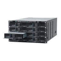
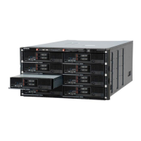
3. Turn on the maintenance mode from web console.
See Maintenance mode on/off procedure on page 4-10 section.
4. Release the two thumbscrews, as shown below.
5. Hold the two thumbscrews and pull the front panel module out of the
server chassis.
6. Remove the USB memory from the failed front panel module.
See
Removing a USB memory on page 5-126 section.
Note: The USB memory removed from the failed front panel module in step 6
is reinstalled to the spare front panel module.
The configuration data of server blade and management module is stored in
it.
Make sure not to misplace it absolutely.
Figure 5-157 Removing a front panel module
Installing a front panel module
1. Put on an anti-static wrist strap.
2. Install the USB memory to the spare front panel module.
See Installing a USB memory on page 5-126 section.
3. Reverse the removal procedure.
4. Turn off the maintenance mode from web console.
See
Maintenance mode on/off procedure on page 4-10 section.
5. Verify that the replacement was successful through the MAR log.
See
Alert information identification procedure on page 4-5 section.
Replacing a USB memory in the front panel module
This procedure describes how to remove a USB memory from the front panel
module.
Replacing parts
5-125
Hitachi Compute Blade 500 Series System Service Manual

 Loading...
