4 Individual remote controls
PC-ART
TCGB0106 rev.0 - 12/2014
148
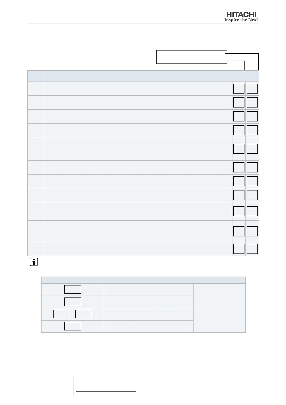
Content of check mode 1
By pressing “” consecutively, the following indications will be displayed.
Indication of temperature, etc.
Category code indication
Step
No.
Temperature indication
1 Indoor unit temperature setting (°C).
b1 22
2 Indoor unit air inlet temperature (°C).
b2 20
3 Indoor unit discharge air temperature (°C).
b3 55
4 Indoor unit heat exchanger liquid piping temperature (°C).
b4 20
5
Remote sensor temperature (°C).
- This is only displayed when connected to a remote sensor.
The display normally shows “--”.
The RPK series cannot connect to a remote sensor. The indication is therefore “--”.
b5 25
6 Outdoor unit ambient temperature (°C). b6 10
7 Indoor unit heat exchanger refrigerant gas piping temperature (°C).
b7 25
8 Outdoor unit evaporating temperature during heating (°C).
b8 02
9
Control information.
- Displays internal remote control information.
For the SET-FREE unit, this indication shows the number of compressors running.
b9 --
10
Discharge gas refrigerant temperature in top of compressor chamber (°C).
- (Example) When several compressors are running, the average temperature of 2 compressors is given.
- If the temperature exceeds 126°C, the indication will read “126”.
bA 41
11 Remote control thermostat temperature.
bb 23
NOTE
Possible abnormal conditions
TEMPERATURE INDICATION FAULT
--
Open circuit on any thermistor except 129
Check that the PCB is not
reading the thermistor incor-
rectly.
Consult the "PCB self-
checking procedure using
the remote control" section
129
Open circuit in compressor discharge thermistor
FF
or
255
Short-circuit in any thermistor except 127
127
Short-circuit in compressor discharge thermistor
During transitory periods, such as on start-up, the “--” or “00” indicator may appear for a limited time.

 Loading...


