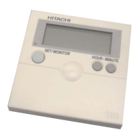
4 Individual remote controls
Receiver kit for wireless remote control
TCGB0106 rev.0 - 12/2014
202
Installation procedure
DANGER
• Turn OFF the power source completely before performing the dip switch setting, installation work and electrical wiring work
for receiver kit. If not, it may cause an electric shock.
• Perform securely the installation work referring to this installation manual. If the installation is not completed, it may cause
injury by falling down the receiver kit.
• Do not install the receiver kit where the ammable gases may generate or enter. It may cause heat generation or a re.
• Perform securely the electrical wiring work. If the electrical work is not completed, heat generation at the connection, a re
or an electric shock may occur.
• Make sure that the electrical wires are securely xed in order not to apply an external force to the terminal connections of
the wirings. If xing is not completed, it may cause heat generation or a re.
CAUTION
• When the receiver kit is attached near lighting which generates the ambient light, it may not receive the signal from the wireless remote
control. Pay attention to the installation position of receiver kit.
• Do not run the wire for receiver kit and wire of 220-240V (power source wire) in parallel. It may cause malfunction of receiver kit by
noise.
1
Perform the installation work for receiver kit while the indoor unit is being mounted.
2
Be sure to turn OFF the power source of indoor unit when the receiver kit is attached after the indoor unit is mounted.
3
Remove the right side cover.
a. Open the air inlet grille. b. Remove the xing screw (M4)
Air inlet Grille
Fixing Screw
c. Push the side cover to 15 mm forward to remove the hooks and the hooking plate.
d. Remove the side cover to lift upward.
Hooking Plate
Position for Fixing Screw
Hooks (3 portions)
4 Remove the remote control switch cover attaching to the lower cover.
a. Insert screwdriver or a stick (maximum f5) into the service hole at the lower right side of lower cover.
b. Press the service hole to remove the remote control switch cover.
2 Remote Control Switch Covers
Press here by screwdriver or a stick to remove
the remote control switch cover
Position for Receiver Kit (It can be attached to
both of right side and left side)

 Loading...