6 Building air conditioning controls
CSNET Manager LT/XT
TCGB0106 rev.0 - 12/2014
547547
6
Explanation of the elds
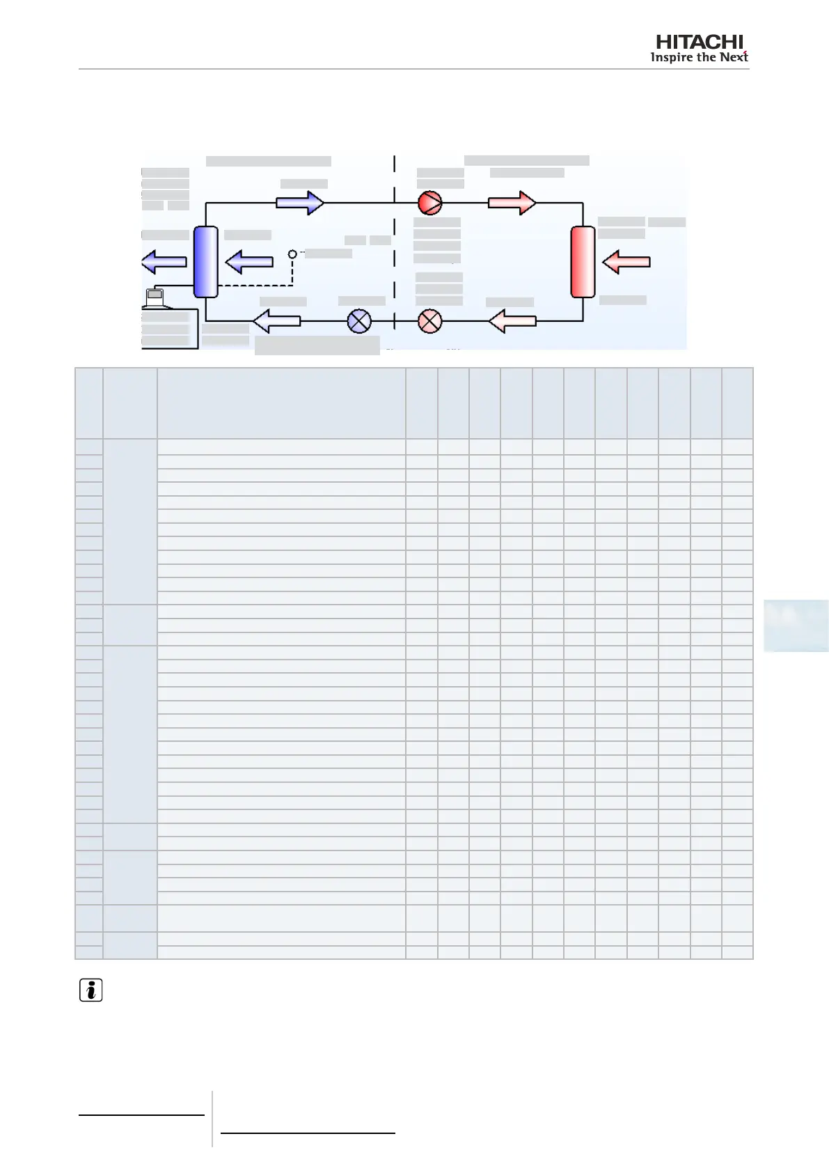
Although all these parameters are available in the 3-tube systems (Set-Free FX), some are not in other systems. These
are indicated in the table.
1
2
3
4
5 6
7
8
9
10
11
12
13
14
15
16
17
18
19
20
21
22
23
24
25
26
27
36
37
28
29
30
31
32
33
34
35
No. Group Description
Units
Utopia G
Utopia N
DC-Inverter
Mini Set-
Free
Set-Free FS
Set-Free FX
DX-Kit
RAS units
KPI Active
KPI Passive
1
Indoor
unit
Model of the indoor unit and its power — O O O O O O O O O O
2 Thermo ON/OFF — O O O O O O O O O —
3 OFF/ON — O O O O O O O O O O
4 Filter time h O O O O O O O — O O
5 Air outlet temperature ºC O O O O O O O — O —
6 Air inlet temperature ºC O O O O O O O O O —
7 Optional remote thermistor (RCS / THM4) (4) ºC O O O O O O O O O —
8 Gas piping temperature ºC — O O O O O O — O —
9 Liquid piping temperature ºC O O O O O O O — O —
10 Expansion valve opening % — O O O O O O — O —
11 Real operation mode ºC O O O O O O O O O
12 Real vent speed — O O O O O O O O O O
13
Remote
control
Setting temperature — O O O O O O O O O O
14 Selected operation mode — O O O O O O O O O O
15 Selected fan speed — O O O O O O O O O O
16
Outdoor
unit
Model of outdoor unit and its power — O O O O O O O — O —
17 Discharge pressure MPa — — — O O O O — O —
18 Suction pressure MPa — — — O O O O — O —
19 Discharge gas overheating (TdSH) ºC — — — O O O O — O —
20 Discharge gas temperature ºC O O O O O O O — O —
21 Compressor frequency Hz — — O O O O O — O —
22 Total consumption of compressors A O O O O O O O — O —
23 Number of compressors operating — O O — O O O O — O —
24 MV1 expansion valve opening % — — O O O O O — O —
25 MV2 expansion valve opening % — — — — (1) O — — — —
26 MV3 expansion valve opening/MVB % — — — — (2) O — — — —
27 Ambient temperature ºC O O O O O O O — O —
28 Evaporating temperature (Heating) ºC O O O O O O O — O —
29
Alarms
Number and description of alarm — O O O O O O O O O O
30 Last cause of compressor stop (3)
— — O O O O O O — O O
31
Others
THM1 ºC — — — — — — O — — —
32 THM2 ºC — — — — — — O — — —
33 PCB1 THM1 (RA) ºC — — — — — — — — O O
34 PCB1 THM2 (OA) ºC — — — — — — — — O O
35
Power
Meter
Power Meter values — O O O O O O — — — —
36
OU
Control
Power control activated —
37 Night mode activated —
O = Available — = Not available
NOTE
(1): Not for FS units of up to 10 HP.
(2): Not for FS units of up to 20 HP.
(3): The value shown does not disappear until the cause of the compressor stop does not change.
(4): THM4 is the remote thermistor. More information on the indoor unit documentation.

 Loading...


