Appendix - Installation of Remote Termination Panels (RTPs) - Analog Input/Digital Input/Digital Output/Analog
Output
224 HC900 Process Controller Installation and User Guide Revision 19
06/14
16 Point AC Digital Input
Step Action
1 ATTENTION: RTP and cables are intended for permanent installation within their own enclosure.
ATTENTION: The RTP combines the two groups of 8 inputs into one group of 16.
Mount RTP cable assembly to HC900 Controller (Figure 92).
• Remove appropriate key tabs from terminal board to allow mating with the module. See page 75.
• Connect desired cable to 16 point AC DI module at controller. Choose from:
900RTC-H010 Remote Terminal High Voltage Cable assembly, 1.0 meters long
900RTC-H025 Remote Terminal High Voltage Cable assembly, 2.5 meters long
900RTC-H050 Remote Terminal High Voltage Cable assembly, 5.0 meters long
• Install 16 point AC DI module label into module connector cover.
• Connect shield drain wire to the grounding bars at the base of the HC900 rack. All field-wiring
shields must be grounded as described in the shield grounding section (page 70).
2 Mount RTP to DIN rail.
• Latch to rail. See page 244.
• Connect cable to RTP
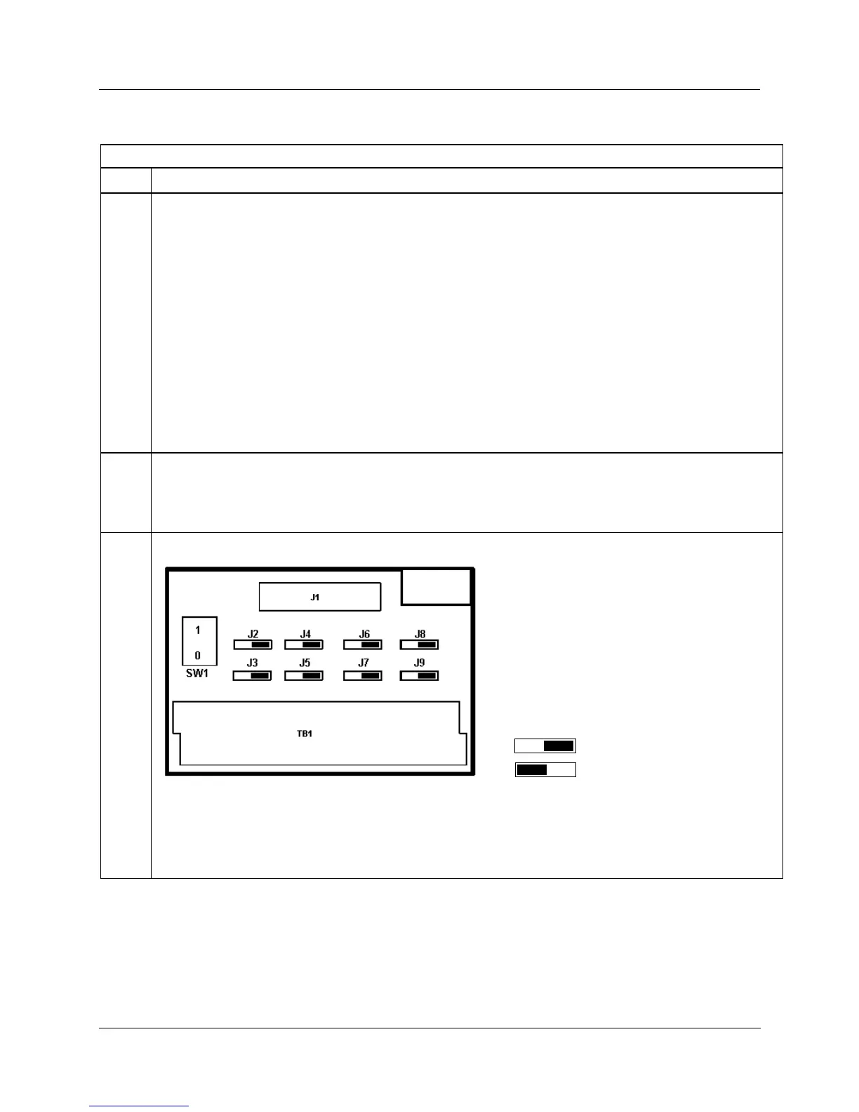
3 Set/verify jumper positions as shown.
Module Removal / Insertion Under Power (RIUP) is supported by turning off Switch SW1 to allow removal of
the module from the rack without causing an arc. See page 73.
ATTENTION: SW1 only disconnects L1, not both sides of the AC powerline.
See page 230 for RTP internal schematic.

 Loading...


