91
# On the LNS, use the display l2tp session command to check the established L2TP sessions.
[LNS] display l2tp session
LocalSID RemoteSID LocalTID State
2041 64 196 Established
Configuration example for client-initiated L2TP tunnel
Network requirements
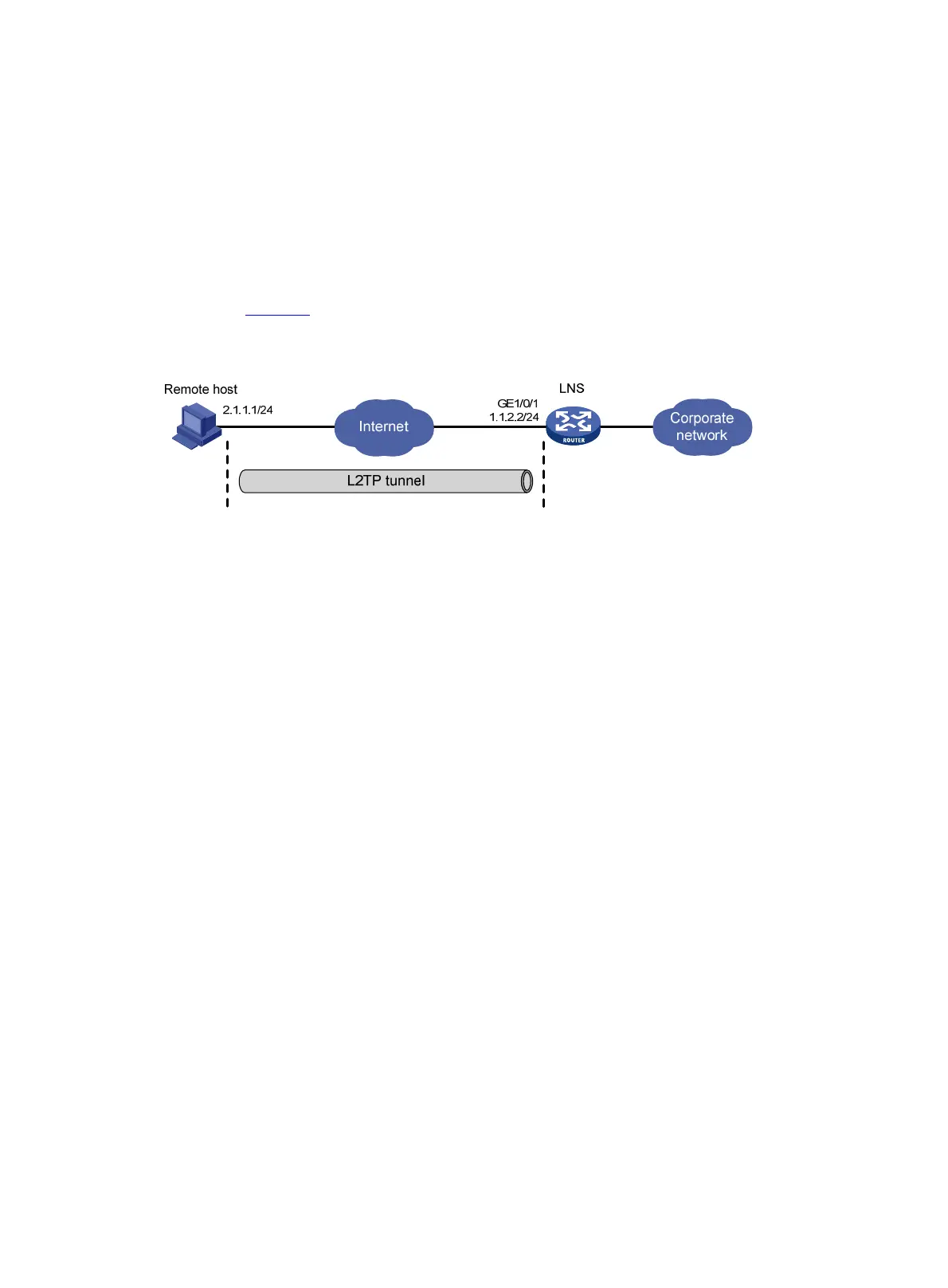
As shown in Figure 33, a PPP user directly initiates a tunneling request to the LNS to access the corporate
network.
Figure 33 Network diagram
Configuration procedure
1. Configure the LNS:
# Configure IP addresses for the interfaces. (Details not shown.)
# Configure the route between the LNS and the remote host. (Details not shown.)
# Create a local user named vpdnuser, set the password, and enable the PPP service.
[LNS] local-user vpdnuser class network
[LNS-luser-network-vpdnuser] password simple Hello
[LNS-luser-network-vpdnuser] service-type ppp
[LNS-luser-network-vpdnuser] quit
# Configure local authentication for PPP users in ISP domain system.
[LNS] domain system
[LNS-isp-system] authentication ppp local
[LNS-isp-system] quit
# Enable L2TP.
[LNS] l2tp enable
# Configure PPP address pool.
[LNS] ip pool aaa 192.168.0.10 192.168.0.20
[LNS] ip pool aaa gateway 192.168.0.1
# Create interface Virtual-Template 1, specify the PPP authentication mode as CHAP, and use the
address pool aaa for the client.
[LNS] interface virtual-template 1
[LNS-virtual-template1] ppp authentication-mode chap domain system
[LNS-virtual-template1] remote address pool aaa
[LNS-virtual-template1] quit
# Create L2TP group 1 in LNS mode.
[LNS] l2tp-group 1 mode lns

 Loading...