244
Task Command
Clear the address-to-DLCI maps
established by InARP.
reset fr inarp [ interface interface-type interface-number [ dlci dlci-number ] ]
Clear statistics of PVCs. reset fr pvc [ interface interface-type interface-number [ dlci dlci-number ] ]
Clear statistics for Frame Relay
IPHC.
reset fr compression iphc { rtp | tcp } [ interface interface-type
interface-number [ dlci dlci-number ] ]
Frame Relay configuration example
Network requirements
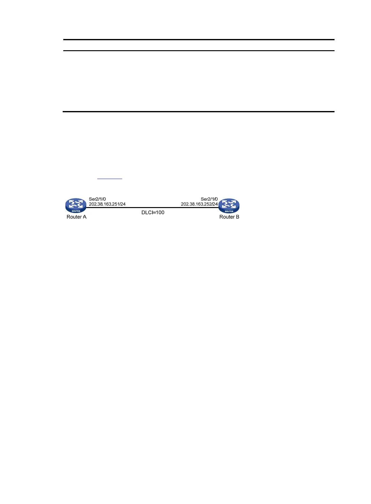
As shown in Figure 74, configure Frame Relay so that Router A and Router B can communicate.
Figure 74 Network diagram
Configuration procedure
(Method 1) Using main interfaces
1. Configure Router A:
# Assign an IP address to interface Serial 2/1/0.
<RouterA> system-view
[RouterA] interface serial 2/1/0
[RouterA-Serial2/1/0] ip address 202.38.163.251 255.255.255.0
# Enable Frame Relay encapsulation on the interface.
[RouterA-Serial2/1/0] link-protocol fr
# Set the type of the interface to DCE.
[RouterA-Serial2/1/0] fr interface-type dce
# Configure a local virtual circuit.
[RouterA-Serial2/1/0] fr dlci 100
2. Configure Router B:
# Assign an IP address to interface Serial 2/1/0.
<RouterB> system-view
[RouterB] interface serial 2/1/0
[RouterB-Serial2/1/0] ip address 202.38.163.252 255.255.255.0
# Enable Frame Relay encapsulation on the interface.
[RouterB-Serial2/1/0] link-protocol fr
# Set the type of the interface to DTE.
[RouterB-Serial2/1/0] fr interface-type dte

 Loading...