146
# Create PVCs, and enable them to carry IP.
[RouterC-ATM2/4/0] pvc to_a 0/60
[RouterC-ATM2/4/0-pvc-to_a-0/60] map ip 202.38.160.1
[RouterC-ATM2/4/0-pvc-to_a-0/60] quit
[RouterC-ATM2/4/0] pvc to_b 0/61
[RouterC-ATM2/4/0-pvc-to_b-0/61] map ip 202.38.160.2
Verifying the configuration
# Use the ping command to verify that the three routers can ping each other successfully. (Details not
shown.)
IPoEoA configuration example
Network requirements
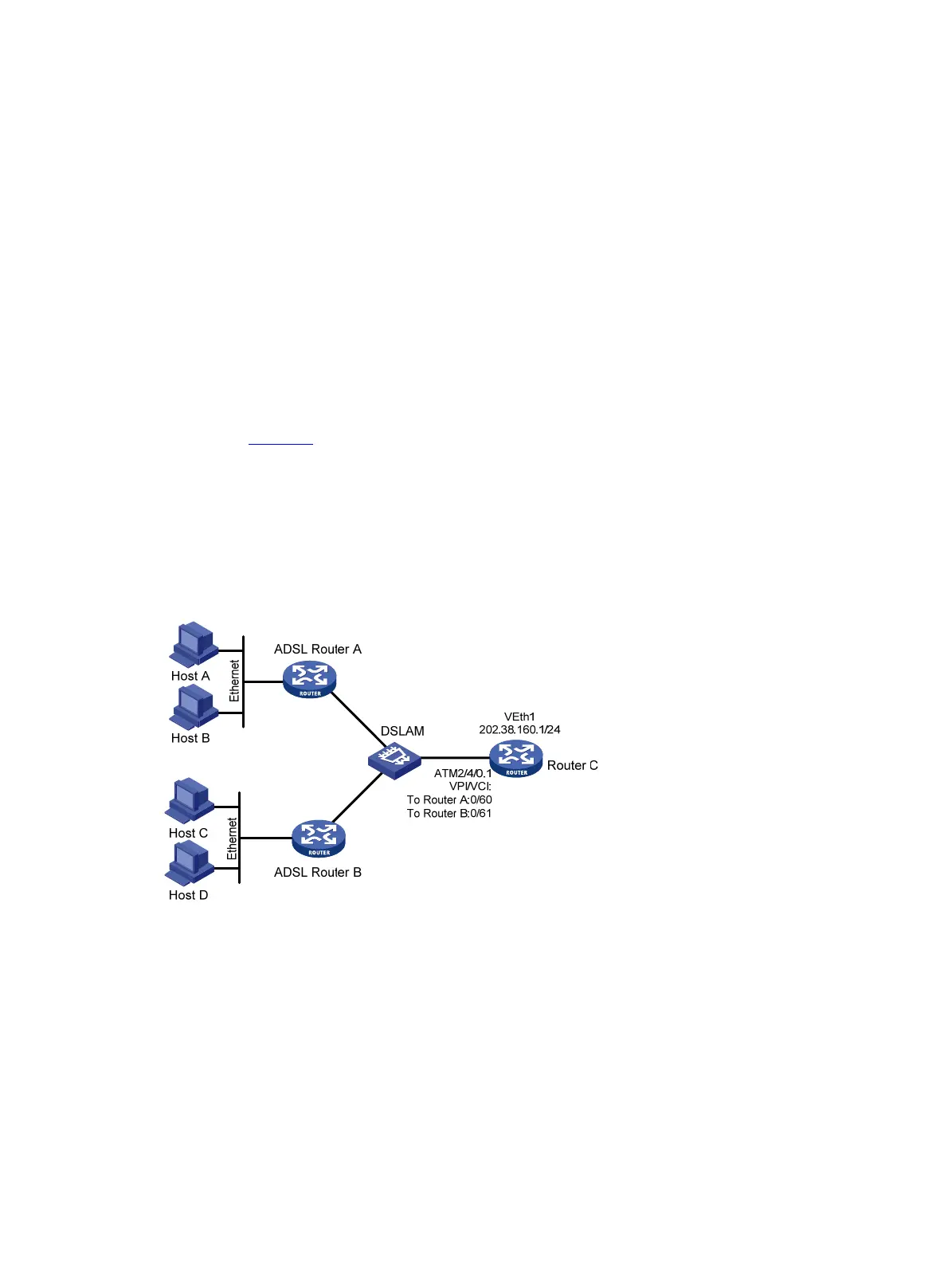
As shown in Figure 47, the hosts in the two Ethernets are connected to the ATM network through ADSL
Router A and ADSL Router B. They communicate with Router C through DSLAM.
The IP address of the VE interface of Router C is 202.38.160.1.
The VPI/VCI values of the two PVCs connecting Router C and DSLAM are 0/60 and 0/61, pointing to
Router A and Router B, respectively.
Both the WAN port of Router C and the DSL interfaces of the ADSL routers use IPoEoA.
Figure 47 Network diagram
Configuration procedure
1. Configure Router C:
# Create a VE interface and configure an IP address for it.
<RouterC> system-view
[RouterC] interface virtual-ethernet 1
[RouterC-Virtual-Ethernet1] ip address 202.38.160.1 255.255.255.0
[RouterC-Virtual-Ethernet1] quit
# Create PVCs, and enable them to carry IPoE.
[RouterC] interface atm 2/4/0.1
[RouterC-ATM2/4/0.1] pvc to_adsl_a 0/60

 Loading...