125
[RouterA-Serial2/3/0:15] dialer route ip 202.38.154.2 8810154
[RouterA-Serial2/3/0:15] dialer-group 1
2. Configure Router B:
# Bundle timeslots into a PRI set on the CE1/PRI interface E1 2/3/0.
<RouterB> system-view
[RouterB] controller e1 2/3/0
[RouterB-E1 2/3/0] pri-set
[RouterB-E1 2/3/0] quit
# Create dialer access group 1 to allow any IP packets to trigger a call setup.
[RouterB] dialer-group 1 rule ip permit
# Assign Serial 2/3/0:15 an IP address.
[RouterB] interface serial 2/3/0:15
[RouterB-Serial2/3/0:15] ip address 202.38.154.2 255.255.0.0
# Enable C-DDR on the interface, configure the route to Router A, and assign the interface to dialer
access group 1.
[RouterB-Serial2/3/0:15] dialer circular enable
[RouterB-Serial2/3/0:15] dialer route ip 202.38.154.1 8810152
[RouterB-Serial2/3/0:15] dialer-group 1
3. Verify the configuration:
# Ping 202.38.154.2 from Router A to verify that the state of a B-channel on E1 2/3/0 changes
to Line up.
# Ping 202.38.154.2 again to verify that the ISDN PRI line transfers data without any losses.
NI-enabled ISDN BRI configuration example
Network requirements
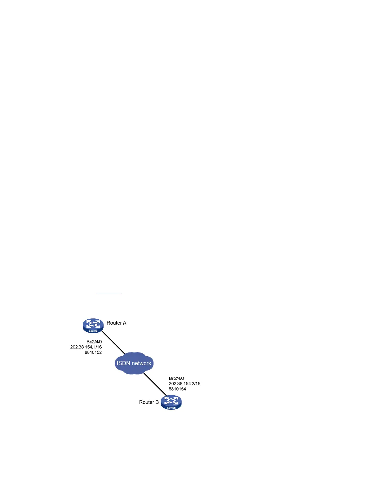
As shown in Figure 41, configure an NI-enabled ISDN BRI line between Router A and Router B for data
transmission.
Figure 41 Network diagram
Configuration procedure
In this example, the ISDN BRI interfaces on Router A and Router B are operating on the user side (the
default). You must configure the ISDN PRI interfaces as the network side on the service provider switches
connected to the routers.

 Loading...