231
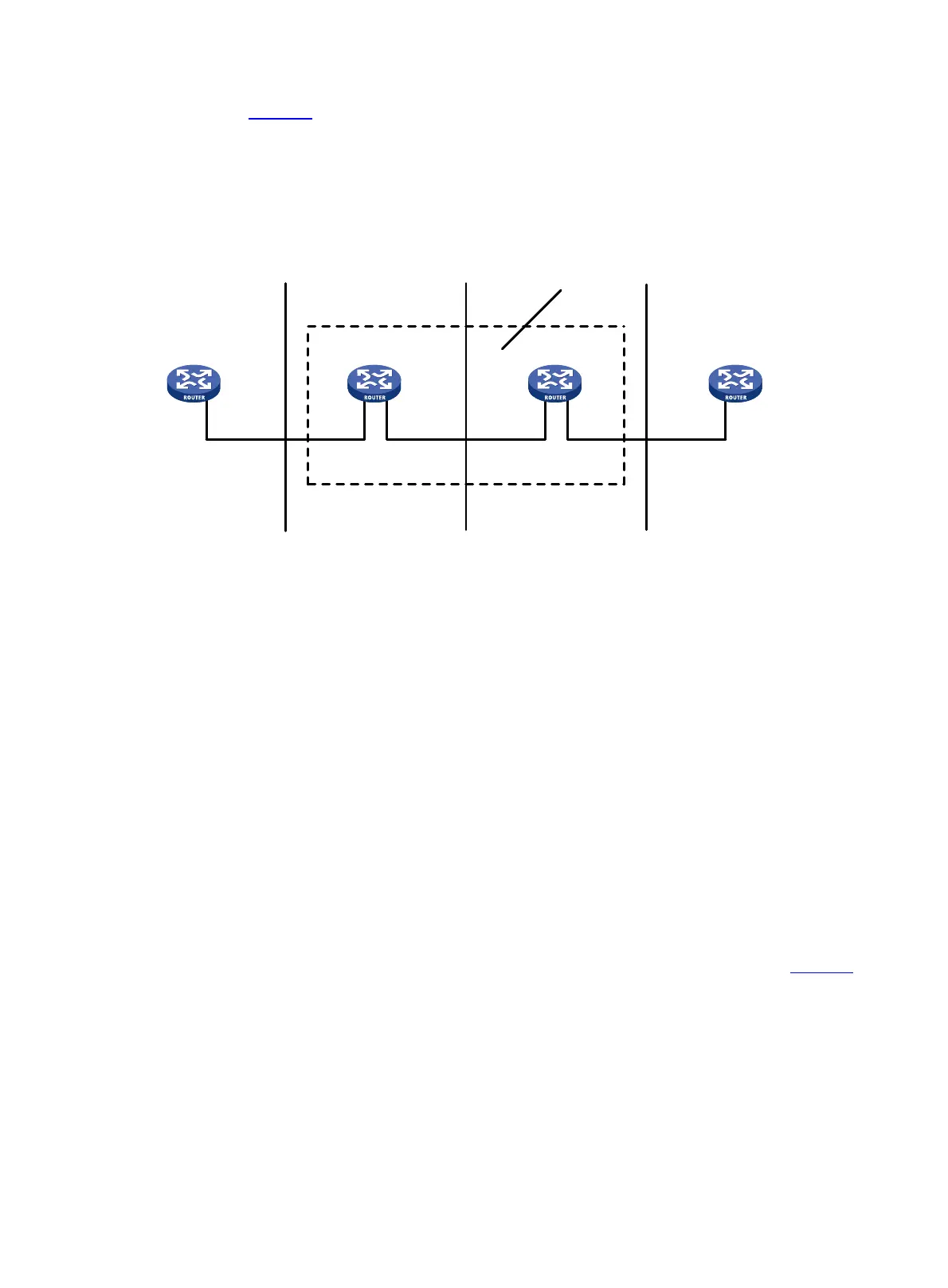
As shown in Figure 71:
• Router B and Router C form a simple Frame Relay network.
• DTE devices Router A and Router D are attached to the network.
The interface type DTE or DCE is identified only for the UNI interfaces. A virtual circuit between two DTE
devices can be assigned different DLCIs on different segments.
Figure 71 Frame Relay network
Virtual circuit
Virtual circuits are logical connections established between two devices. Depending on how they are
established, virtual circuits include the following types:
• Permanent virtual circuit (PVC)—A PVC is manually configured or dynamically learned through the
LMI negotiation.
• Switched virtual circuit (SVC)—An SVC is dynamically established between two devices through
calls. The network provides data transmission services on established SVCs. The terminal users can
terminate an SVC through clearing the call.
Unlike SVCs, PVCs rarely break or disconnect. PVCs are used more than SVCs.
DLCI
A DLCI uniquely identifies a virtual circuit on a physical link and has local significance only for that link.
A DLCI can be used on different physical ports to address different virtual circuits. A virtual circuit
between two DTE devices can be addressed with different DLCIs at the two ends, as shown in Figure 71
.
Because the virtual circuits in a Frame Relay network are connection oriented, each DLCI on a physical
port is destined for a different peer device. DLCIs are the Frame Relay addresses of peer devices.
The maximum number of PVCs that can be created on a Frame Relay interface is 1024. The user
configurable DLCIs for the PVCs are in the range 16 to 1007. Other DLCIs are reserved. For example,
DLCI 0 and DLCI 1023 are reserved for the LMI protocol to transfer control messages.
Ser2/1/1Ser2/1/1Ser2/1/0
DLCI=100
DTE DTEDCE
Ser2/1/0
Ser2/1/0 Ser2/1/0
NNI NNI DCE
Router A Router B Router C Router D
DLCI=200 DLCI=300
Frame relay
network
UNI
UNINNI

 Loading...