37
56 bytes from 200.1.1.1: icmp_seq=1 ttl=128 time=2.594 ms
56 bytes from 200.1.1.1: icmp_seq=2 ttl=128 time=2.739 ms
56 bytes from 200.1.1.1: icmp_seq=3 ttl=128 time=1.738 ms
56 bytes from 200.1.1.1: icmp_seq=4 ttl=128 time=1.744 ms
--- Ping statistics for 200.1.1.1 ---
5 packet(s) transmitted, 5 packet(s) received, 0.0% packet loss
round-trip min/avg/max/std-dev = 1.738/2.402/3.197/0.576 ms
# Display the address pools on Serial 2/1/0 of Router A.
[RouterA-Serial2/1/0] display ip pool
Group name: AAA
Pool name Start IP address End IP address Free In use
aaa 200.1.1.10 200.1.1.20 10 1
In use IP addresses:
IP address Interface
200.1.1.10 S2/1/0
The output shows that one IP address of aaa has been assigned.
MP binding mode configuration examples
Network requirements
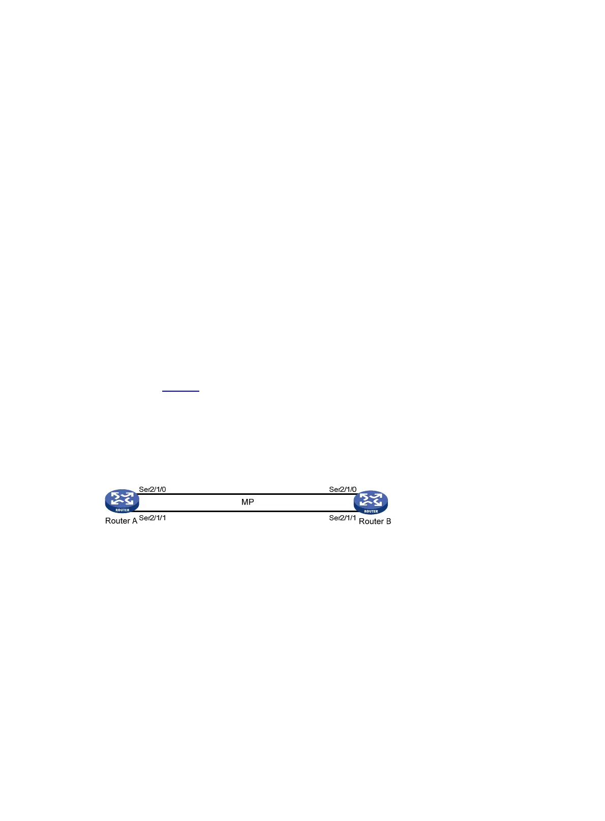
As shown in Figure 9, to enable MP for Serial 2/1/0 and Serial 2/1/1, use one of the following
methods:
• Bind the physical interfaces to a VT interface.
• Associate remote usernames with a VT interface.
• Configure an MP-group interface.
Figure 9 Network diagram
Configuration procedure
(Method 1) Binding the physical interfaces to a VT interface
1. Configure Router A:
# Create a VT interface, and configure an IP address for it.
<RouterA> system-view
[RouterA] interface virtual-template 1
[RouterA-Virtual-Template1] ip address 8.1.1.1 24
[RouterA-Virtual-Template1] quit
# Configure Serial 2/1/1.
[RouterA] interface serial 2/1/1
[RouterA-Serial2/1/1] link-protocol ppp
[RouterA-Serial2/1/1] ppp mp virtual-template 1
[RouterA-Serial2/1/1] quit

 Loading...