145
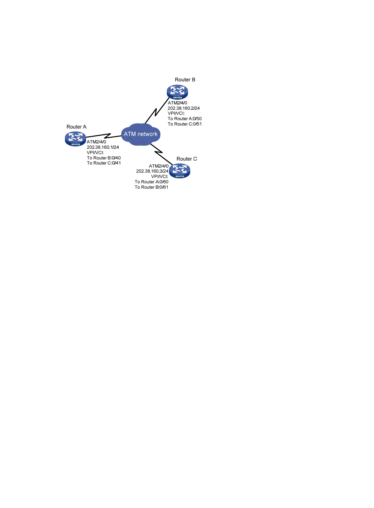
• The VPIs/VCIs of Router C are 0/60 and 0/61, connected to Router A and Router B, respectively.
All the PVCs on ATM interfaces of the three routers operate in IPoA application mode.
Figure 46 Network diagram
Configuration procedure
1. Configure Router A:
# Enter the view of interface ATM 2/4/0 and configure an IP address for it.
<RouterA> system-view
[RouterA] interface atm 2/4/0
[RouterA-ATM2/4/0] ip address 202.38.160.1 255.255.255.0
# Create PVCs, and enable them to carry IP.
[RouterA-ATM2/4/0] pvc to_b 0/40
[RouterA-ATM2/4/0-pvc-to_b-0/40] map ip 202.38.160.2
[RouterA-ATM2/4/0-pvc-to_b-0/40] quit
[RouterA-ATM2/4/0] pvc to_c 0/41
[RouterA-ATM2/4/0-pvc-to_c-0/41] map ip 202.38.160.3
2. Configure Router B:
# Enter the view of interface ATM 2/4/0 and configure an IP address for it.
<RouterB> system-view
[RouterB] interface atm 2/4/0
[RouterB-ATM2/4/0] ip address 202.38.160.2 255.255.255.0
# Create PVCs, and enable them to carry IP.
[RouterB-ATM2/4/0] pvc to_a 0/50
[RouterB-ATM2/4/0-pvc-to_a-0/50] map ip 202.38.160.1
[RouterB-ATM2/4/0-pvc-to_a-0/50] quit
[RouterB-ATM2/4/0] pvc to_c 0/51
[RouterB-ATM2/4/0-pvc-to_c-0/51] map ip 202.38.160.3
3. Configure Router C:
# Enter the view of interface ATM 2/4/0 and configure an IP address for it.
<RouterC> system-view
[RouterC] interface atm 2/4/0
[RouterC-ATM2/4/0] ip address 202.38.160.3 255.255.255.0

 Loading...