122 EDGE Pro Ti CNC Instruction Manual 807660
Maintenance and Diagnostics
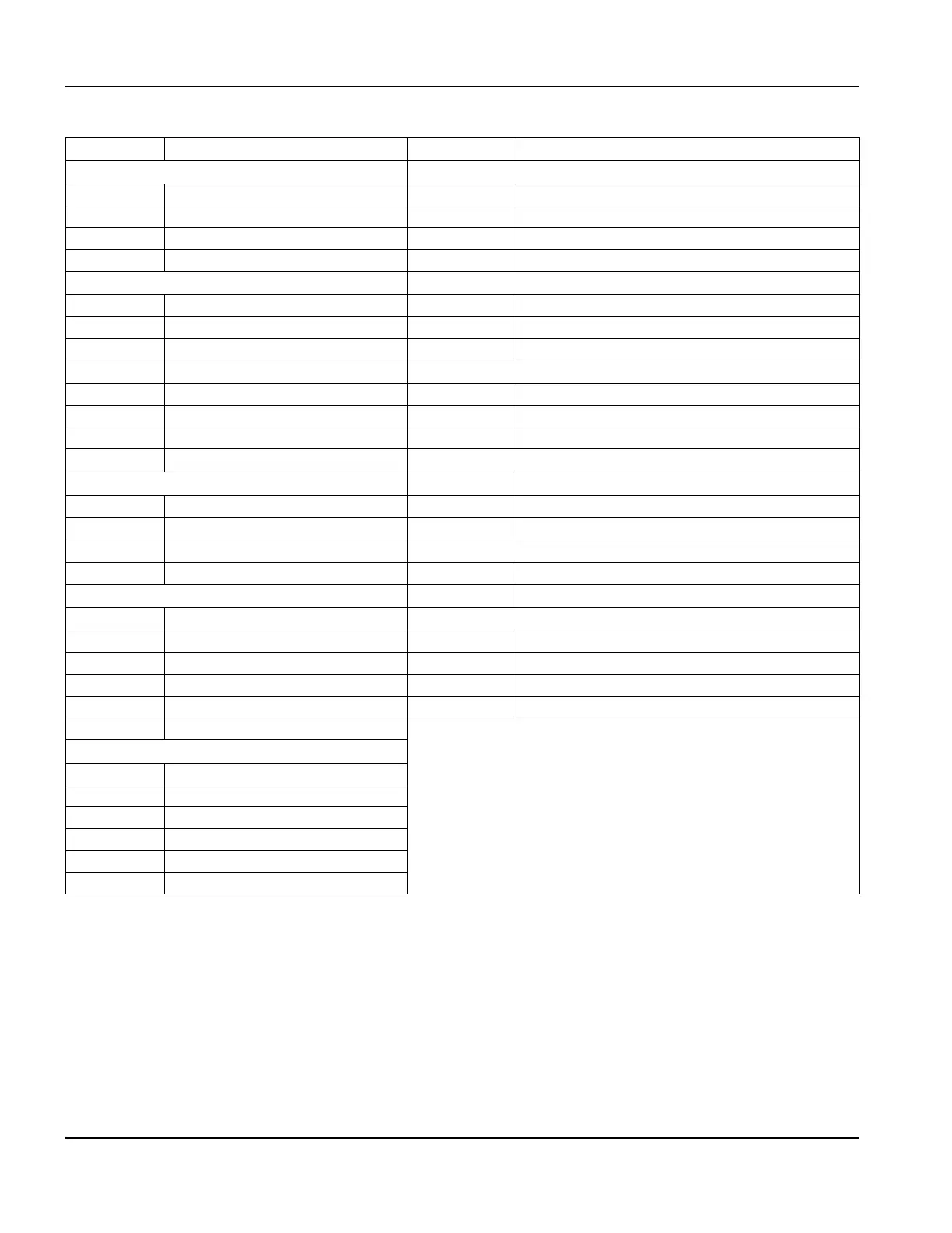
Power distribution board (141153)
Table 23 Pinouts for J1 to J12
Pin no. Signal Pin no. Signal
J1 Clean DC out J6 Clean DC out
1 Logic +5 V fused 1 Logic +5 V fused
2 Logic -12 V fused 2 Logic -12 V fused
3 Logic +12 V fused 3 Logic +12 V fused
4 Logic ground 4 Logic ground
J2 Clean DC in J7 Utility
1 Logic +5 V 1 Fan disable
2 Logic +12 V 2 Field power good
3 Logic +12 V 3 Logic ground
4 Logic +12 V
J8 Display
5 Logic -12 V 1 Earth ground
6 Logic ground 2 Line 2
7 Logic ground 3 Line 1
8 Logic ground
J9 ATX power supply
J3 External cooling
1 Line 1
1 Fan +24 V 2 Line 2
2 Fan Interlock 2 3 Earth ground
3 Fan Interlock 1
J10 AC in (from surge board J2)
4 Field ground 1 Line 2
J4 Field DC out
2 Line 1 switched
1 Field ground
J11 and J12 HDD
2 +24 V 1 Logic +12 V
3 +5 V 2 Logic ground
4 -12 V 3 Logic ground
5 +12 V 4 Logic +5 V
6 Field ground
J5 Field DC out
1 Field ground
2+24 V
3+5 V
4-12 V
5+12 V
6 Field ground