EDGE Pro Ti CNC Instruction Manual 807660 53
Installation
AC power
AC power
Power input
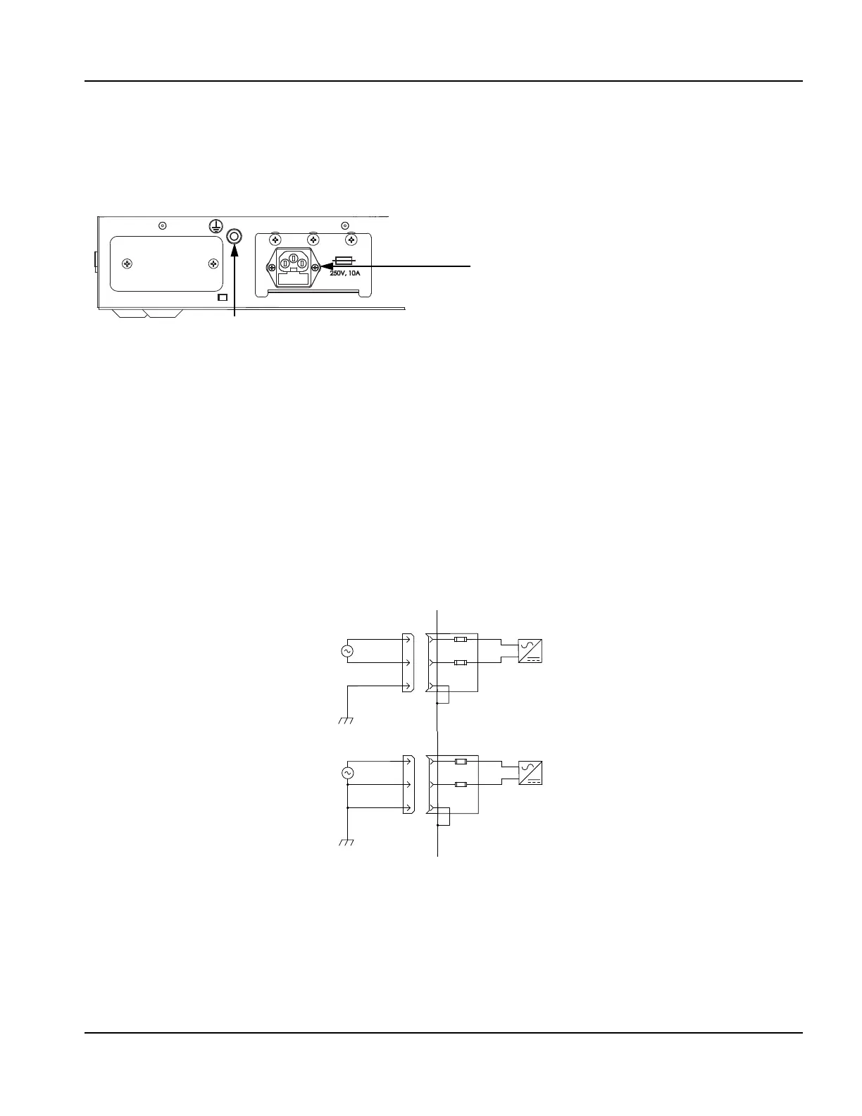
Figure 14 illustrates the power input connector on the rear of the EDGE Pro Ti CNC.
Figure 14 AC power input connector
Note: The AC power cable must be plugged into an AC branch circuit with a 20-A limit.
Power cable
An AC power cable is standard equipment for North America, and is shipped with the EDGE Pro Ti CNC. For other
regions, use a power cord that has an IEC–60320–C13 end which meets the requirements of local code and power
connections.
For more electrical specifications, see “System specifications” on page 33. Figure 15 shows examples of how power
cables can be created.
Note: The fuse block holds two 250 V, 10 A, slow-blow, 5 mm x 20 mm fuses.
Figure 15 Input VAC wiring examples
AC Power connector
Voltage range: 115 to 240 V, single phase
Fuse size: 250 V, 10 A, slow-blow, 5 mm x 20 mm
Ground nut and lock washer 1/4 in. – 20
EDGE Pro Ti CNC
Power entry module:
2 Fuses: 250 V, 10 A, slow blow, 5 x 20 mm
EDGE Pro Ti CNC
Power entry module:
2 Fuses: 250 V, 10 A, slow blow, 5 x 20 mm
Customer-supplied
power 220 VAC
Customer-supplied
power 120 VAC
L1 – line
L2 – line
PE ground
L1 – line
L2 – neutral
PE ground