EDGE Pro Ti CNC Instruction Manual 807660 57
Installation
Emergency stop (E-stop) connection
Emergency stop (E-stop) connection
The E-stop connector provides the interface for an E-stop button with a separate reset switch to meet local safety
regulations.
Safety audit
A safety audit must be conducted before the system is installed. All requirements for redundancy, monitoring, and
scheduled testing for safety circuits that result from the audit must be implemented.
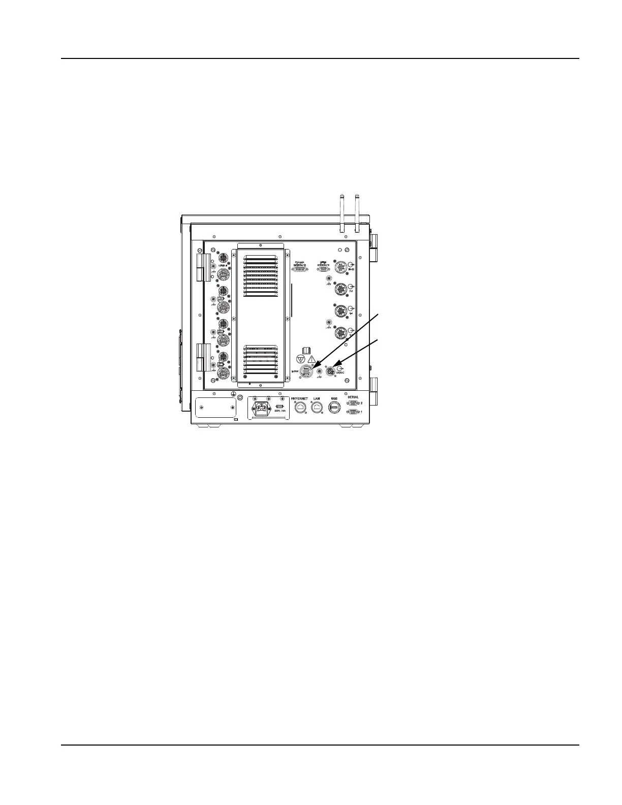
Figure 19 Location of the EDGE Pro Ti E-stop connector
The table manufacturer must supply and install the E-stop logic functions, E-stop switch and reset switch to insure that
they are in complete compliance with national and local safety regulations and the configuration of the system.
Installation of the circuitry and switches can be done using safety relays or PLCs, as necessary. A safety PLC may be
preferred if advanced functionality or advanced machine and factory integration is required. The E-stop interface on the
rear of the EDGE Pro Ti enclosure has been tested with the following commercially available components:
• Safety relay (003239)
• Normally closed, dual pole, single throw E-stop switch (428025)
• Normally open, momentary reset switch (428026)
The E-stop interface must be satisfied to engage the motors. If the E-stop is not satisfied, the motors will not spin. Figure
20 on page 58 shows a possible design for an E-stop circuit, including the circuitry that exists within the EDGE Pro Ti
CNC and circuitry using an Allen Bradley safety relay.
Note:
• The safety relay is powered by 24 VDC from pins 1 and 10 of the E-stop connector on the CNC.
• The sensor circuit is wired for 2-channel E-stop monitoring with LS1 and LS2 monitor contacts in series.
• The start circuit is wired for manual, monitored activation.
• When the LED is illuminated, it indicates that the machine is disabled.
E-stop connector
24 V auxiliary power output