EDGE Pro Ti CNC Instruction Manual 807660 59
Installation
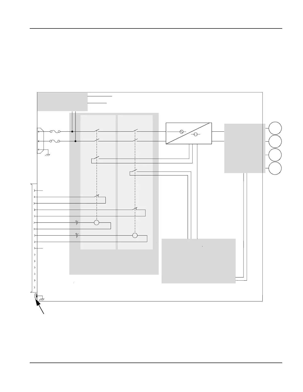
Emergency stop (E-stop) connection
EDGE Pro Ti safety circuit
The EDGE Pro Ti CNC has a safety circuit that allows table manufacturers to implement E-stop or other safety measures
according the needs of their customers and their local and national safety regulations. Figure 21 illustrates this circuit.
Figure 20, illustrates an example of an E-stop design that might connect to the safety circuit within the EDGE Pro Ti
CNC through the E-stop connector on the rear panel of the CNC.
Figure 21 EDGE Pro Ti safety circuit
Power distribution
board
(page 121)
250 V, 10 A slow
blow fuse
1 +24 V
2 E-Stop monitor 1A
3 E-Stop monitor 1B
7 24 V coil 1B
6 24 V coil 1A
5 E-Stop monitor 2B
4 E-Stop monitor 2A
10 Field ground
9 24 V coil 2B
8 24 V coil 2A
AC
DC
Power
good
Servo board
(page 137)
current control
and
Z axis brake
M1
M2
M3
M4
60 V enable
E-stop
12 Not connected
11 Not connected
15 Not connected
14 Not connected
13 Not connected
Power good bit
E-stop input bit
I/O board to CNC
motherboard
(page 120)
Surge and safety
relay board
(page 142)
EDGE Pro Ti CNC
Relay LS1 with
force-guided
contacts
Relay LS2 with
force-guided
contacts
Normally open
Normally open
Normally closed
Normally closed
J6
CPC
EMI ground screw. Connect the ring terminal
from the E-stop cable shield.
16 Cable shield