EDGE Pro Ti CNC Instruction Manual 807660 73
Installation
I/O connection
Configuring I/O
The EDGE Pro Ti I/O circuitry provides inputs through optoisolators and outputs through relays. Contacts for both
normally open and normally closed outputs are available.
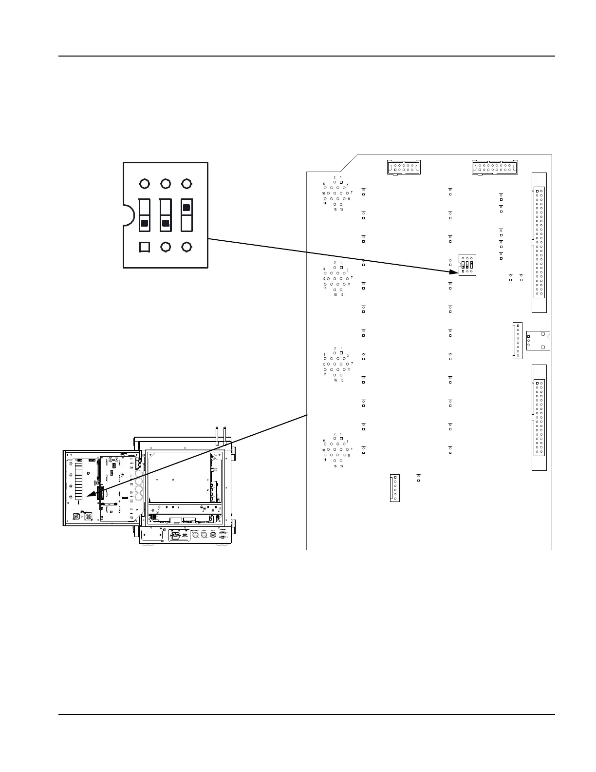
Use the DIP switch on the Relay I/O board (141278) to configure I/O.
Figure 35 I/O configuration DIP switch
Shared inputs
General inputs 11 and 12 are shared with the limit switch inputs. However, the Sensor Ti lifter does not use limit switches
so position 1 and 2 must remain in the OFF (default) position. In this case, inputs 11 and 12 are available on the I/O
interface CPC connector as general purpose inputs.
If you are using a custom lifter with upper and lower limit switches, change position 1 and 2 to the ON position and select
sourced input mode (position 3 in the OFF position); this changes all general purpose I/O to sourced inputs. Wire the
limit switches to the lifter interface DB-9 connector.
Regardless of the type of lifter you install, do not wire to both the CPC inputs 11 and 12 and to the DB-9 lifter interface
connector inputs 11 and 12 simultaneously.
1
OFF
2
3
Default settings on the DIP switch
ON
12 3
On
Use lower limit
switch
Upper limit
switch
Dry contact
inputs (default)
Off
I/O 12
(default)
I/O 11
(default)
Sourced inputs