128 EDGE Pro Ti CNC Instruction Manual 807660
Maintenance and Diagnostics
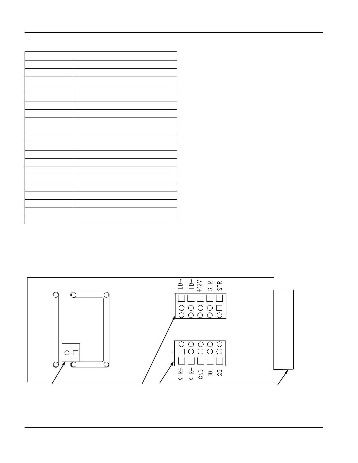
Plasma interface board (141267)
Table 27 Pinouts for J3
Plasma interface board (141267)
The plasma interface board is a component of the plasma interface assembly (228256) described on page 143.
Figure 68 Plasma interface board
J3 To Serial COM3 and COM4
1 Ground
2DR_A
3/RXD_INA
4TS_A
5 TXD_OUTA
6TS_A
7DR_A
8 Ground
9 Ground
10 Not connected
11 Ground
12 DR_B
13 /RXD_INB
14 TS_B
15 TXD_OUTB
16 TS_B
17 DR_B
18 Ground
19 Ground
20 Not connected
1
2
345
1
2
345
These pins are connected and receive arc
voltage signals (-) from the control board in
the plasma system
15-pin D-sub connector (P1) for the
plasma interface cable to the CNC
J1 and J3 carry I/O signals between the
CNC and the control board in the
plasma system
J2
J3
J1
1
2