EDGE Pro Ti CNC Instruction Manual 807660 143
Maintenance and Diagnostics
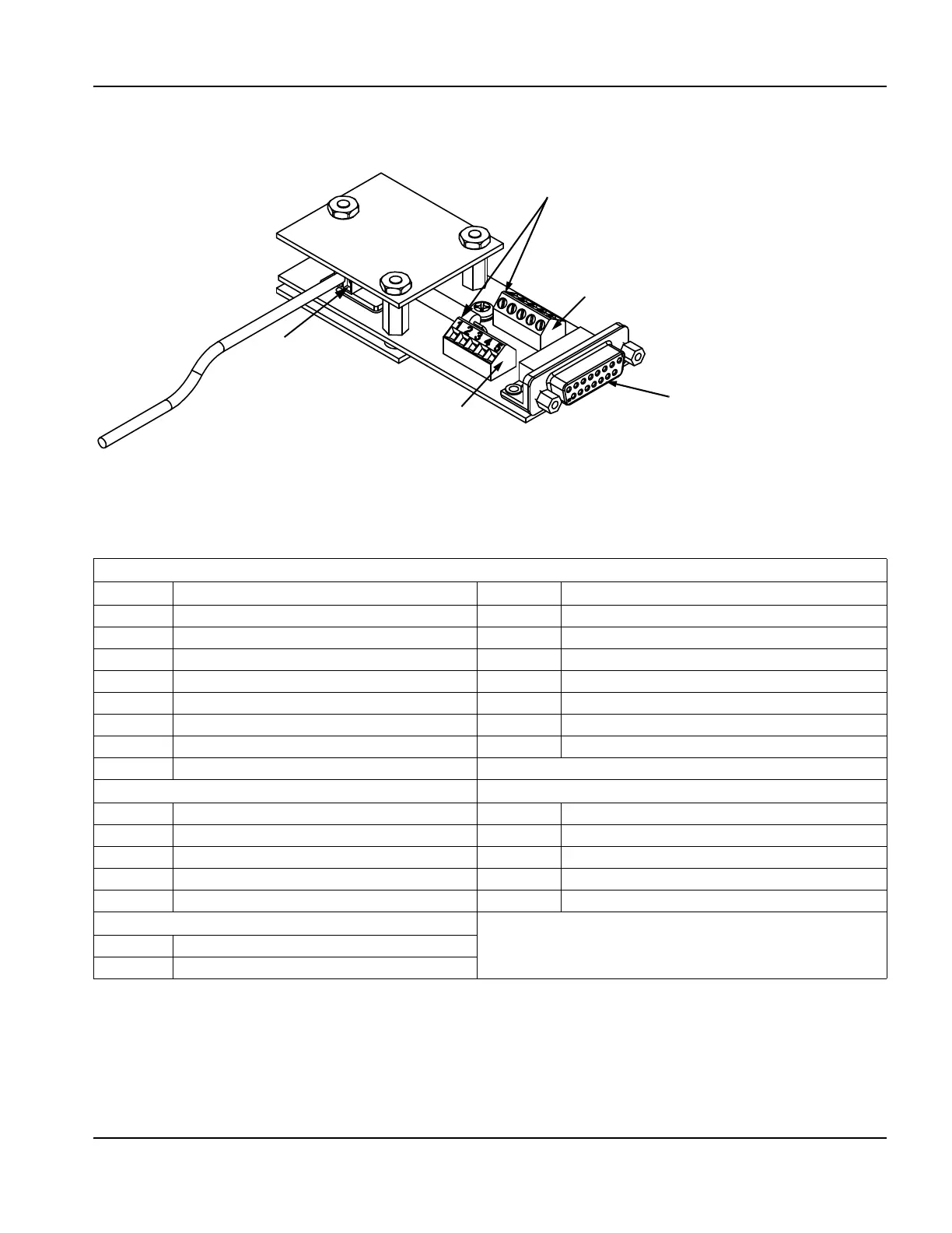
Plasma interface assembly (228256)
Plasma interface assembly (228256)
Figure 73 Plasma interface board (141267)
Table 45 Pinouts on the plasma interface board
P1 Plasma interface cable connector
Pin no. Signal Pin no. Signal
1 +12 V 9 +12 V
2 Plasma start+ 10 Plasma start-
3 Hold ignition+ 11 Hold ignition-
4 Transfer+ 12 Transfer-
5 Field common 13 Field common
6 Field common 14 Field common
7 Field common 15 Arc voltage
8 Ground
J1 Terminal block for power supply I/O J3 Terminal block for power supply I/O
1 Plasma Start+ 1 Transfer+
2 Plasma Start- 2 Transfer-
3 +12 VDC 3 Field ground
4 Hold Ignition+ 4 Not connected
5 Hold Ignition- 5 Not connected
J2 Terminal block for arc voltage
1 Arc voltage 250 V
2 Arc voltage 250 V
J2
Arc voltage signals to the
plasma system
J1
J3
Terminal blocks for I/O signals between the CNC and
plasma system
P1
15-pin D-sub connector for the
plasma interface cable to the CNC