66 EDGE Pro Ti CNC Instruction Manual 807660
Installation
Motor connection
Regeneration circuit
When rapid deceleration of a motor brake creates additional, excessive voltage on the 60 VDC bus, the regeneration
circuit turns on a 10 Ohm resistor to divert the excess braking energy and lower the voltage. When the bus voltage
decreases, the resistor turns off.
When the resistor circuit turns on or off, the circuit sends an input signal to Phoenix software to report the change in
status. This signal is fixed as Input 14 in Phoenix software.
Users can monitor the regeneration circuit in the Watch Window on the Main screen in Phoenix software by turning on
the Regen Active status in the Watch Window setup. The oscilloscope function also allows users to monitor the
operation of the regeneration circuit. For more information on setting up the Watch Window or using the oscilloscope
function, refer to the Phoenix Software Operator’s Manual (806400).
The regeneration circuit should not be active for more than 25% of a single cut. See “Troubleshooting” on page 112 for
more information.
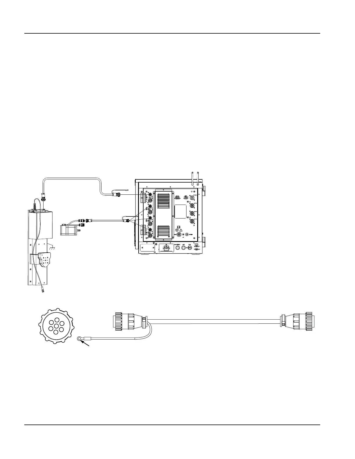
Motor cable
Figure 28 Motor cable from the CNC to the axes
Figure 29 Motor cable
Motor cable to
axes 1, 2, and 3
Motor cable to
axis 4
Diameter = 11.6mm (0.458 in.)
Bend radius = 150 mm (6.0 in.)
Connect to motor connector ground stud
1
7