62 EDGE Pro Ti CNC Instruction Manual 807660
Installation
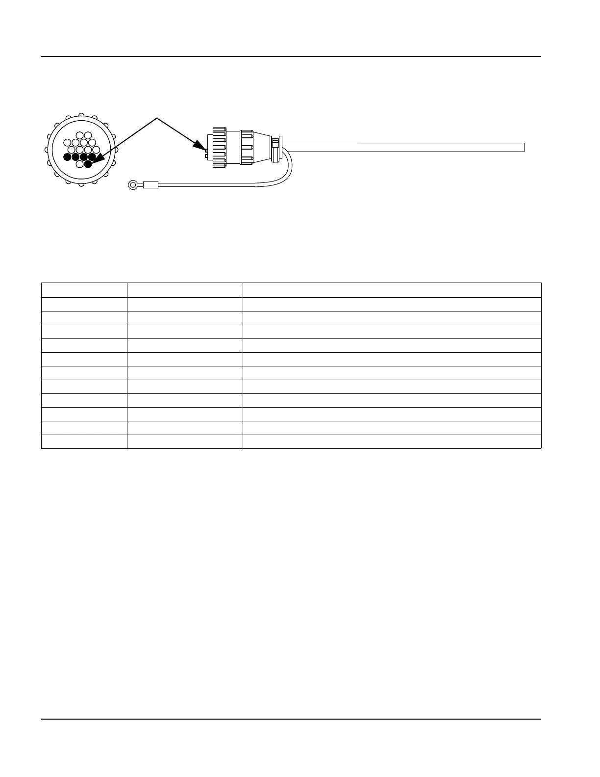
Emergency stop (E-stop) connection
E-stop cable
Figure 24 E-stop cable
Table 6 E-stop cable pinouts
Use the following information to order E-stop cables.
To create a custom cable, order the connector kit (428046).
Pin no. Wire color Signal
1 Brown +24 V field
2 Orange E-stop monitor 1A
3 Blue E-stop monitor 1B
4 Violet E-stop monitor 2A
5 Grey E-stop monitor 2B
6 White 24 V coil 1A
7 Green 24 V coil 1B
8 Yellow 24 V coil 2A
9 Red 24 V coil 1B
10 Black Field ground
11–16 Not connected
Part Number Length
223365 3.05 m (10 ft)
223366 6.08 m (20 ft)
223367 7.62 m (25 ft)
223368 10.66 m (35 ft)
223369 15.25 m (50 ft)
Key plugs in 11 – 15
1
16
36
10
14