EDGE Pro Ti CNC Instruction Manual 807660 63
Installation
Motor connection
Motor connection
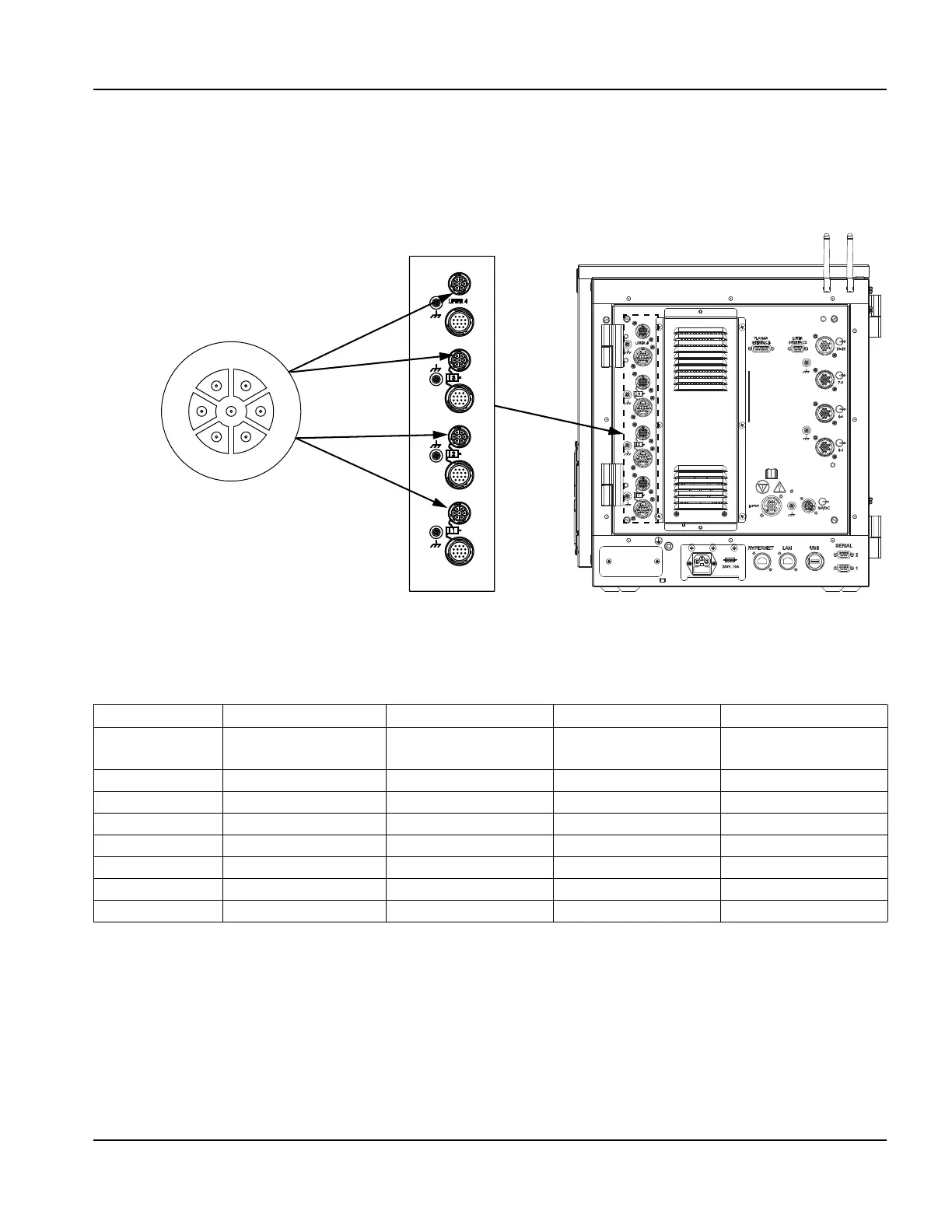
Install the motor cables between the Axis 4 motor connector and the motor connector on the Sensor Ti and between the
Axis 3, Axis 2, and Axis 1 motor connectors on the rear of the EDGE Pro Ti and the motor connector on the remaining
axis motors (031143). For more information about the motor cable, see Motor cable on page 66.
Figure 25 Ti motor interfaces
Table 7 Pinouts for motor interfaces
Note:
• Select brushed or brushless mode for the motor on each axis using the DIP switch on the Ti servo board
(141281) inside the back door of the CNC. A single EDGE Pro Ti can have both brush and brushless
motors if switches are set properly. For more information, see Axis configuration on page 64.
• Axis 4 is the only axis that supports a lifter. It is the only axis that supplies the 24 VDC that is required to
disable a lifter’s electromechanical power-off brake.
• For optimum noise immunity, cable shields should be tied externally to the CNC enclosure.
Pin no. Axis 4 – Lifter Axis 3 (Dual gantry) Axis 2 (Y or X) Axis 1 (X or Y)
Motor
connectors
J16 J15 J14 J13
1 Motor/brake A Motor/brake A Motor/brake A Motor/brake A
2 Motor/brake B Motor/brake B Motor/brake B Motor/brake B
3 Motor/brake C Motor/brake C Motor/brake C Motor/brake C
4 Brake+ (24 VDC) Brake+ (dry contact) Brake+ (dry contact) Brake+ (dry contact)
5 Brake- (common) Brake- (dry contact) Brake- (dry contact) Brake- (dry contact)
6 Shield Shield Shield Shield
7 Shield Shield Shield Shield
Axis 1
12
5
3
76
Axis 2
Axis 3
Axis 4 – lifter
Motor connector